An automatic water control valve for horizontal wells

A technology for water control valves and horizontal wells, applied in wellbore/well valve devices, wellbore/well parts, sealing/isolation, etc., can solve problems such as limited tool use and complicated operations, and increase flow resistance , Enhanced oil recovery and easy operation

Active Publication Date: 2019-08-23
SOUTHWEST PETROLEUM UNIV
View PDF4 Cites 0 Cited by
  • Summary
  • Abstract
  • Description
  • Claims
  • Application Information

AI Technical Summary

Problems solved by technology

These three ICDs are all passive controllers, and the additional differential pressure loss needs to be designed before going into the well, and cannot be changed after going into the well, and the fluid production along the wellbore in the actual reservoir is constantly changing, which limits the use of the tool and make the job more complex

Method used


Image

  • An automatic water control valve for horizontal wells
  • An automatic water control valve for horizontal wells
  • An automatic water control valve for horizontal wells

Examples


Embodiment 1

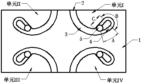
[0022] Explain in detail figure 1 Take unit I in as an example: when the oil-water mixed phase flows into the first-stage diversion tank 3 through the inlet 2, because the water phase density is higher than the oil phase, it will be separated into a single-phase oil-water phase by rotation, such as figure 2 As shown, the water phase is mainly concentrated on the outside of the primary diversion groove 3, and the oil phase is mainly concentrated on the inside of the primary diversion groove 3, and the closer to the outlet 5, the more fully the oil-water miscible phase separation; finally the oil phase directly along the outlet 5 flows out, the water phase will continue to flow along the secondary diversion groove 4 for a certain distance before flowing out along the outlet 5, which increases the frictional resistance of the water phase along the way, while the oil phase is not affected, thereby achieving the purpose of water control.

[0023] The inlet 2 and the outlet 5 of th...

Embodiment 2

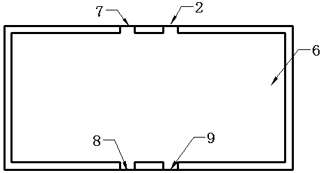
[0026] Explain in detail figure 1 as well as image 3 For example: such as figure 1 As shown, the valve base 1 has four identical units: I, II, III, and IV. Each unit can play a certain role in water control. When the four units are assembled together, the water control effect will be better, that is, a This kind of automatic water control valve for horizontal wells can achieve better water control effect in the unit area of ​​the wellbore, and is suitable for wells with large liquid production.


PUM


Abstract

The invention relates to a horizontal well automatic water control valve. The horizontal well automatic water control valve mainly comprises a valve base 1 and a valve cover 6; the valve base 1 comprises a unit I, a unit II, a unit III and a unit IV which are the same, and the four units are provided with flow guide grooves with the same structure correspondingly; and the flow guide grooves conduct water control by utilizing the following principles that (1) a density difference exists between oil and water, and an oil-water mixed phase can be separated when rotating; and (2) streamwise friction can be generated when fluid flows in the flow guide grooves. The unit I in the valve base 1 is taken as an example to conduct specific explaining: when flowing into a first-stage flow guide groove 3 through an inlet 2, the oil-water mixed phase can be separated into oil and water single phases through rotating, wherein the oil phase flows out directly along an outlet 5, the water phase can continue to flow for a certain distance along a second-stage flow guide groove 4 and then flows out along the outlet 5, thus the streamwise friction of the water phase is increased, and therefore the purpose of controlling water is achieved. The horizontal well automatic water control valve has the beneficial effects that the horizontal well automatic water control valve has no movable component, and is suitable for a sand producer; and, meanwhile, filtrational resistance of a producing area with the high water content can be increased, and the purposes of balancing a fluid producing profile and enhancing the recovery efficiency are achieved.

Description

technical field [0001] The invention relates to an automatic water control valve for a horizontal well, belonging to the technical field of oil and gas field development. Background technique [0002] At present, thin layer oil reservoirs, bottom water oil reservoirs, fractured oil reservoirs and shallow water and deep water oil and gas reservoirs are mainly exploited through horizontal wells and extended reach wells. Due to the influence of flow, the liquid production profile is unbalanced, which leads to premature water breakthrough in oil and gas reservoirs, and ultimately shortens the life of oil and gas wells and reduces the production of oil and gas reservoirs. [0003] ICD (Inflow Control Device) is a new well completion tool used to balance the inflow dynamics of horizontal wellbore. The sand surface pressure drop of each section of the section changes, and then a relatively balanced injection-production profile is obtained. At present, there are three main types o...

Claims


Application Information

Patent Timeline
Patent Type & Authority Patents(China)
IPC IPC(8): E21B34/08
Inventor 李海涛王科李留杰罗伟
Owner SOUTHWEST PETROLEUM UNIV
Why Eureka
Try Eureka