Clavicular hook locking bone plate

A bone plate, clavicle technology, applied in the direction of outer plate, fixator, internal bone synthesis, etc., can solve the problems of incorrect reduction, fracture, and fixation failure of the scapula

Inactive Publication Date: 2017-10-24
A PLUS BIOTECH
View PDF11 Cites 0 Cited by
  • Summary
  • Abstract
  • Description
  • Claims
  • Application Information

AI Technical Summary

Problems solved by technology

Although this kind of parallel design (the hook is parallel to the bone plate) can solve the problem of dislocation of the clavicle joint, however, the number of locking screws locked by the aforementioned bone fixator is too large, so that the hook against the inner surface of the scapula is blocked The scapula is overstressed, making the scapula incorrectly repositioned and causing other complications, such as fixation failure, acromial wear, shoulder discomfort, etc. Fracture of plate / pin
[0005] In order to solve the above-mentioned problem of incorrect scapula repositioning caused by the hook pushing against the hook, the current solution is to make the hook and the bone plate form an included angle. However, although there is an included angle between the hook and the bone plate Solve the problem that the hook part holds against the scapula, but how to reduce the stress exerted by the bone plate on the bone and how to continuously friction and reduce the wear and tear of the clavicle or scapula are still problems that need to be solved urgently

Method used


Image

  • Clavicular hook locking bone plate
  • Clavicular hook locking bone plate
  • Clavicular hook locking bone plate

Examples


Embodiment Construction

[0035] The implementation of the present invention will be illustrated by specific examples below, and those skilled in the art can easily understand the efficacy and advantages of the present invention from the content disclosed in this specification. Moreover, the present invention can also be used and implemented by other specific embodiments, and various details described in this specification can also be applied based on different requirements, and various modifications or changes can be made without departing from the spirit of the present invention.

[0036] The present invention will be described in terms of preferred embodiments and viewpoints. Such descriptions explain the structure of the present invention in detail, and are only used for illustration rather than to limit the patent scope of the present invention. Therefore, in addition to the preferred embodiment in the description, the present invention can also be widely implemented in other embodiments.

[0037]...


PUM


Abstract

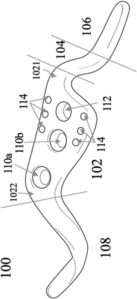
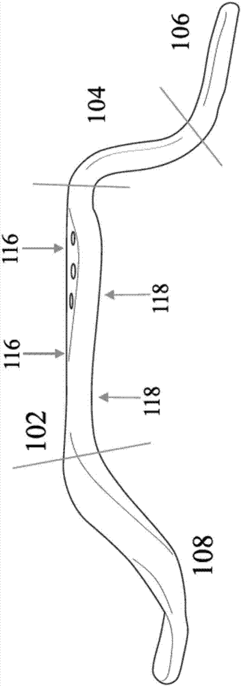
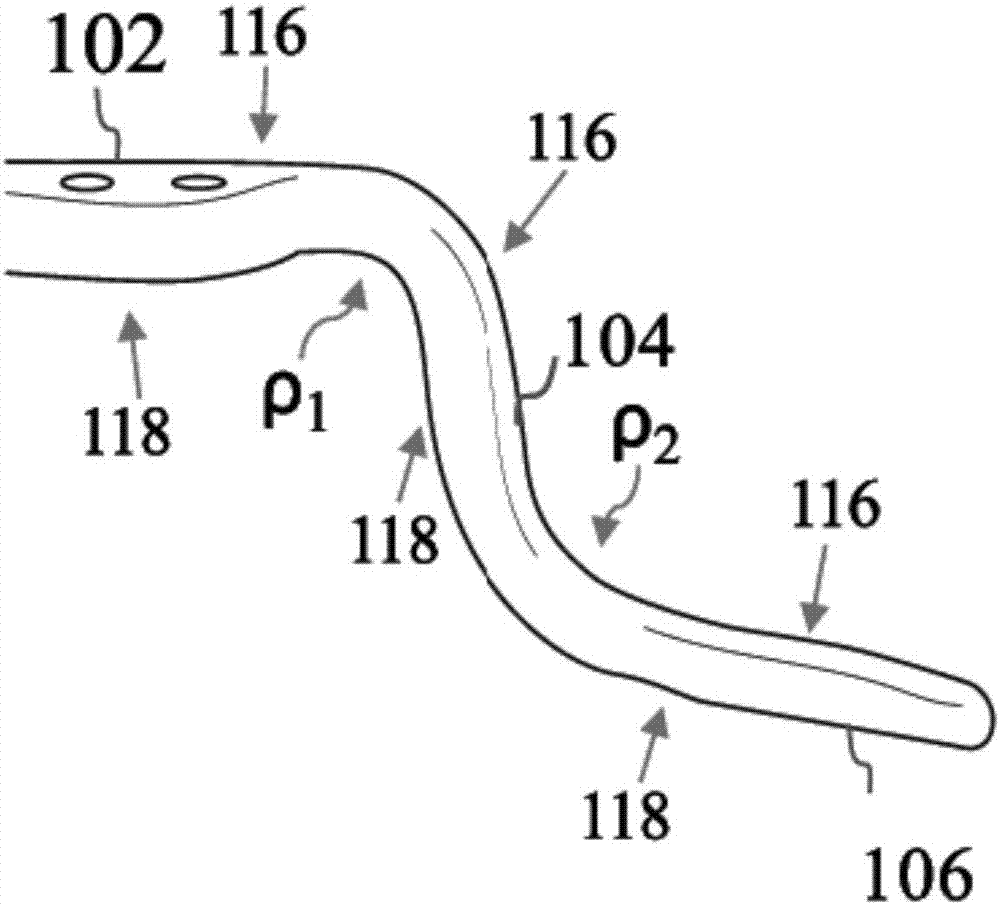
The invention discloses a clavicular hook locking bone plate which comprises a main body, a bending part, a hook part, a winding part, a first side and a second side, wherein the main body further comprises a front end and a rear end and comprises a first pressing hole, a second pressing hole and a locking hole; one end of the above bending part is connected with the front end of the main body; the hook part is connected with the other end of the bending part; the winding part is connected with the rear end of the main body, and the above hook part, the bending part, the main body and the winding part are integrated in sequence; the first side and the second side are respectively arranged on outside and inside of the above bone plate, wherein the first pressing hole, the second pressing hole and the locking hole pass through the bone plate from the first side to the second side.

Description

technical field [0001] The invention relates to a bone plate for fixing the clavicle, in particular to a clavicle hook locking bone plate. Background technique [0002] The bones of different parts of the human body have different shapes and complex structures. In the event of fractures and other injuries, the medical treatment and rehabilitation methods usually need to be given appropriate treatment based on the bone structure of the injured part. When the fractured part is close to the joint When it is not suitable to use plaster fixation, bone plates and bone nails are usually used as fixation for fracture treatment. [0003] Take the clavicle as an example. The clavicle is located at the position where the human body connects the scapula and the sternum. The clavicle is the only bony support connecting the upper limbs and the trunk. The clavicle is slender and S-shaped. Flat, and due to the slender shape of the clavicle, the clavicle is also one of the bones most prone ...

Claims


Application Information

Patent Timeline
Patent Type & Authority Applications(China)
IPC IPC(8): A61B17/80
CPCA61B17/8061
Inventor 付中国吴开兴罗翔炜黄胜隆廖健雄陈文全
Owner A PLUS BIOTECH
Why Eureka
Try Eureka