Fixing device for preventing expansion of boiler connecting pipeline and guiding

A technology for connecting pipes and fixing devices, which is applied to the components of steam boilers, steam boilers, pipe supports, etc. It can solve the problems of difficult selection of spring hangers, easy failure and jamming, and large space occupation, so as to save space, Save cost and reduce the effect of welding pressure

Pending Publication Date: 2017-10-20
HARBIN HAGUO BOILER ENG TECH
View PDF9 Cites 1 Cited by
  • Summary
  • Abstract
  • Description
  • Claims
  • Application Information

AI Technical Summary

Problems solved by technology

[0003] The present invention solves the problem that the spring hanger of the existing boiler connection pipeline fixing device is difficult to select, easily restricts the free expansion of the pipeline, and is prone to failure and jamming after thermal expansion, inconvenient installation, large space occupation, high cost and the assembly and replacement of support beams. Difficult problems, and then provide a fixing device that solves the expansion and guiding of boiler connecting pipes

Method used


Image

  • Fixing device for preventing expansion of boiler connecting pipeline and guiding
  • Fixing device for preventing expansion of boiler connecting pipeline and guiding
  • Fixing device for preventing expansion of boiler connecting pipeline and guiding

Examples


specific Embodiment approach 1

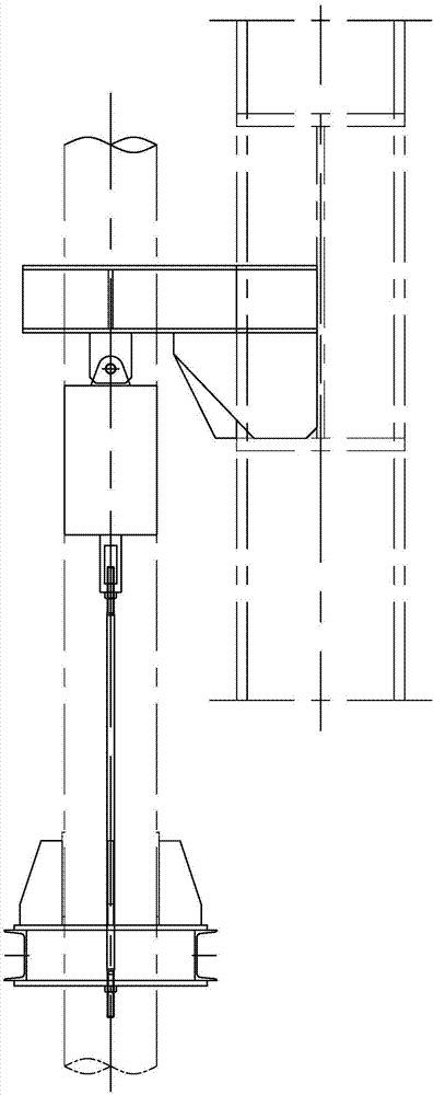
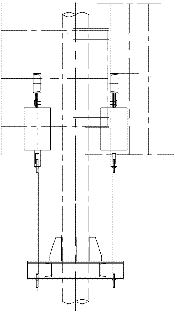
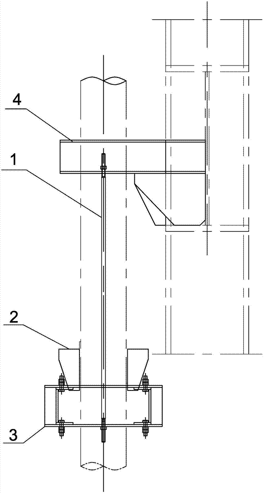
[0007] Specific implementation mode one: combine image 3 , Figure 4 , Figure 5 Explain that a fixing device for solving the expansion and guiding of boiler connecting pipes in this embodiment includes a boom 1, a support rib 2, a support beam 3 and a bracket 4, the upper end of the boom 1 is detachably connected to the bracket 4, and the lower end is connected to the support beam 3 detachable connection, the support rib plate 2 is fixed on the connection pipe and is located on the upper part of the support beam 3, the connection pipe passes through the center of the support beam 3, the support beam 3 has a gap 5, the support rib plate 2 is stuck on the gap 5 and It can drive the support beam 3 to move horizontally.

specific Embodiment approach 2

[0008] Embodiment 2: The supporting ribs 2 in this embodiment are four ribs with a slope, fixedly connected to the connecting pipe, and the surface where the supporting ribs 2 contact with the bottom of the notch 5 is an inclined plane. The inclined plane forms an acute angle with the support beam 3, and the inclined plane extends in the expansion direction of the connecting pipeline. With such an arrangement, the expansion of the pipeline can drive the support beam to move back and forth in the length direction of the waist-shaped hole through the support rib plate with a slope, so as to eliminate the influence of thermal expansion. Others are the same as the first embodiment.

specific Embodiment approach 3

[0009] Specific implementation mode three: combination Figure 5 Note that the support beam 3 in this embodiment includes a side beam 3-1 and a sliding beam 3-2, two waist-shaped holes are opened on both sides of the side beam 3-1, and two round holes are opened on both sides of the sliding beam 3-2. The hole is connected with the side beam 3-1 and the sliding beam 3-2 by the bolt through the round hole and the waist-shaped hole, and the side beam 3-1 and the sliding beam 3-2 can relatively slide in the waist-shaped hole. In this way, the expansion of the pipeline can drive the sliding beam 3-2 to move along the length direction of the waist-shaped hole on the side beam 3-1. The supporting beam is detachable and assembled by bolts, which is convenient for positioning and assembly, and is easy to replace. Only the bolts and nuts need to be replaced to improve safety. Others are the same as those in Embodiment 1 or 2.


PUM


Abstract

The invention provides a fixing device for preventing expansion of a boiler connecting pipeline and guiding, and relates to a pipeline fixing device. The problems that the model of a spring hanger of a fixing device of an existing boiler connecting pipeline can not be selected easily, free expansion of the pipeline is likely to be limited, the fixing device is likely to be out of order and jammed after thermal expansion, installation is not convenient, the occupied space is large, the cost is high, and assembly and replacement of a supporting beam are difficult are solved. The fixing device comprises a suspender, a supporting rib plate and a supporting beam. The upper end of the suspender is detachably connected with a support, the lower end of the suspender is detachably connected with the supporting beam, and the supporting rib plate is fixed on a connecting pipeline and located on the upper portion of the supporting beam; and the connecting pipeline penetrates through the center of the supporting beam, a notch is formed in the supporting beam, and the supporting rib plate is clamped on the notch and can drive the supporting beam to make horizontal movement. The fixing device for preventing expansion of the boiler connecting pipeline and guiding is mainly used for fixing boiler connecting pipelines.

Description

technical field [0001] The invention relates to a pipe fixing device, in particular to a fixing device for solving the expansion and guiding of boiler connecting pipes. Background technique [0002] At present, the hanging form of the connecting pipe of the boiler body is as follows: figure 1 , figure 2 As shown, it welds the bracket on the boiler column and beam, and hangs the spring hanger under the bracket. The spring hanger is connected to the support beam through the suspender, and the four ribs on the connecting pipe are supported on the support beam, because the pipeline The medium inside is high-temperature steam, and there will be corresponding displacement and thermal stress relative to the fixed point. Therefore, a spring hanger, a support beam and a hanger are used to pull the spring in the spring hanger to absorb the expansion of the steam pipe. Although this structure can Absorb the expansion of the pipeline, but there will be errors when selecting the sprin...

Claims


Application Information

Patent Timeline
IPC IPC(8): F22B37/20F24H9/00F16L3/133
CPCF16L3/133F22B37/204F24H9/0005
Inventor 王健申志佳翟闯席晶
Owner HARBIN HAGUO BOILER ENG TECH
Why Eureka
Try Eureka