Curve orbit system with sliding blocks having independent driving force

A technology of curved guide rail and driving force, applied in the field of curved guide rail system, can solve the problems of increasing power consumption, increasing the weight of the motion system, easy to break the belt, etc., to achieve the effect of reducing the outer diameter, reducing production, and convenient lubrication

Active Publication Date: 2017-10-20
FOSHAN GONGXIN PRECISION MACHINERY CO LTD
View PDF8 Cites 5 Cited by
  • Summary
  • Abstract
  • Description
  • Claims
  • Application Information

AI Technical Summary

Benefits of technology

This innovation allows for flexibility when designing a guiding track used by robots or other devices. It uses separate power sources instead of relying solely upon one source like cams or levers. Additionally, it eliminates problems associated with traditional systems due to their rigidity. Overall, this technology improves efficiency and accuracy during movement across surfaces while reducing costs compared to current methods.

Problems solved by technology

This patented technical problem addressed in this patents relates to improving the precision and efficiency when machining complicated parts such as metal pipes used for transportations due to their lengthy paths caused by friction from moving along rails. Existing methods involve adding extra equipment like punch guides (pilot tools) or linkage arrangements involving cables, leading to increased costs associated with maintaining accurate alignment and reduced operational capabilities.

Method used


Image

  • Curve orbit system with sliding blocks having independent driving force
  • Curve orbit system with sliding blocks having independent driving force
  • Curve orbit system with sliding blocks having independent driving force

Examples


Embodiment Construction

[0038] The mechanism and working principle of the present invention will be described in detail below in conjunction with the accompanying drawings. In order to better illustrate this embodiment, some components in the drawings will be omitted, enlarged or reduced, and do not represent the size of the actual product; for those skilled in the art, some known structures and their descriptions in the drawings may be omitted. understandable. The same or similar reference numerals correspond to the same or similar components.

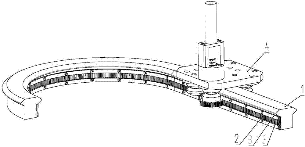
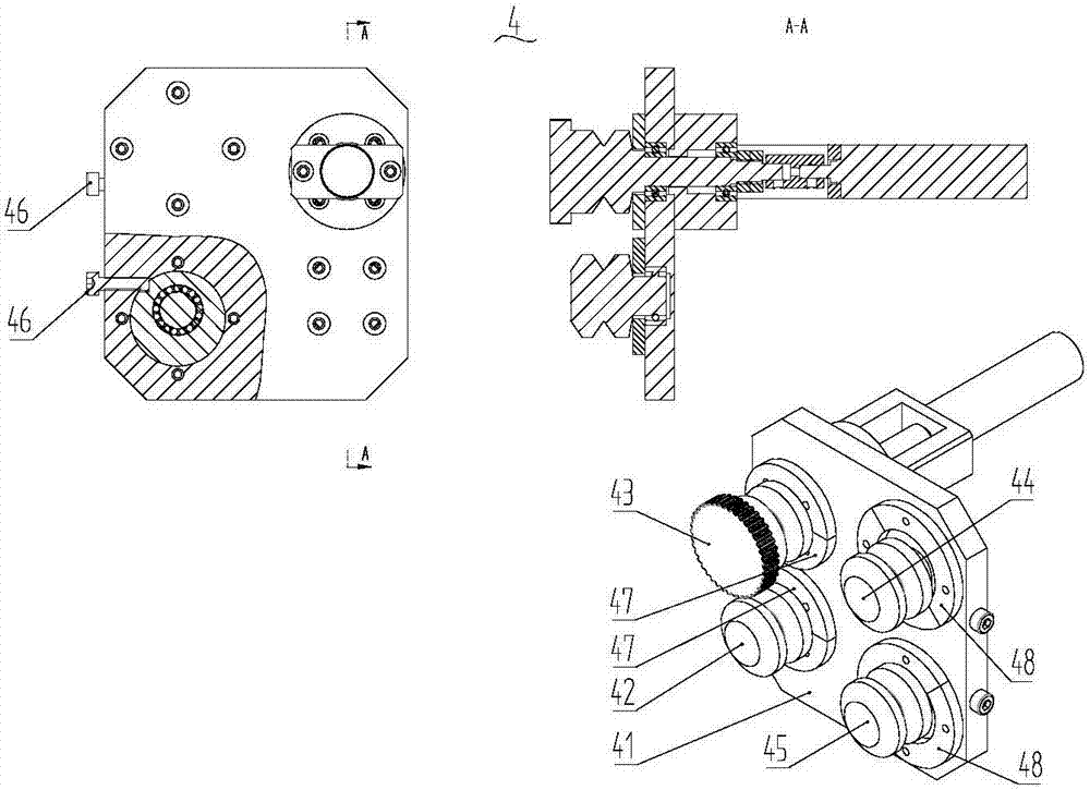
[0039] See Figure 1-6 As shown, the present invention provides a curved guide rail system with an independent driving force for the slider, which is characterized in that it includes a curved slide rail 1, a toothed belt 2 arranged on one side of the curved guide rail 1, and a belt at the upper end and the lower end of the toothed belt 2 The pressing strip 3 on the surface is arranged on the slider 4 above the curved slide rail 1; the slider 4 includes a ...


PUM


Abstract

The invention discloses a curve orbit system with sliding blocks having independent driving force. The curve orbit system comprises a curve orbit, a toothed belt arranged on one side of the curve orbit, pressing strips arranged on belt surfaces of the upper and lower ends of the toothed belt, and the sliding blocks arranged above the curve orbit, wherein each sliding block comprises a pulley fixing plate, a fixed pulley, a driving wheel assembly, an adjustable pulley A, an adjustable pulley B, pressing plates A and pressing plates B; and the driving assembly comprises a toothed pulley, bearings arranged on the toothed pulley, bearing pedestals arranged on the bearings in a sleeving manner, a motor seat arranged on the bearing pedestals, a motor arranged on the motor seat, a shaft coupler arranged on the motor and the toothed pulley, and locking nuts arranged on one side of the shaft coupler. Transmission teeth on the curve orbit of the curve orbit system adopt the toothed belt which is convenient to produce and mount; the production, mounting and maintenance cost is greatly reduced; pulley balls are arranged at positions at the shaft ends of pulley shafts far away from sliding chutes, so that the outer diameter of each pulley can be reduced; the sliding blocks have the independent driving force, so that all the sliding blocks in the curve orbit system are more flexible and free.

Description


Claims


Application Information

Patent Timeline
Owner FOSHAN GONGXIN PRECISION MACHINERY CO LTD
Why Eureka
Try Eureka