Approach channel retaining wall repairing structure and method

A technology for repairing structures and approach channels. It is applied in water conservancy projects, sea area projects, buildings, etc. It can solve problems such as collapse, potential safety hazards, and easy stress on straight sides, achieving the effect of small space and high timeliness

Pending Publication Date: 2017-10-20
江苏省科佳工程设计有限公司
View PDF5 Cites 4 Cited by
  • Summary
  • Abstract
  • Description
  • Claims
  • Application Information

AI Technical Summary

Problems solved by technology

[0004] The side facing the water flow of this kind of bank revetment structure is a straight edge. When there are cracks and staggered joints at the bank revetment settlement joints, and the side facing the water flow is repaired, the impact of the water flow, the erosion of the ship's waves and the soil behind the revetment will Under the action of various forces such as pressure, the straight edge is prone to collapse due to force, and there are potential safety hazards in the construction process

Method used


Image

  • Approach channel retaining wall repairing structure and method
  • Approach channel retaining wall repairing structure and method

Examples


Embodiment 1

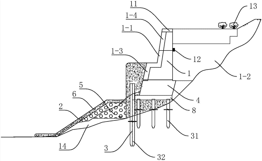
[0040] Embodiment 1: A kind of revetment repair structure of approach channel, such as figure 1 As shown, it includes a body of wall 1 vertically on the ground. The side of the body of wall 1 facing the water is the water-facing surface 1-1, and the side facing the ground is the back-water surface 1-2. Prefabricated square piles 3. Wherein, the prefabricated square piles 3 independent from the wall 1 are detachable piles 32 , and the prefabricated square piles 3 located below the wall 1 and fixedly connected with the wall 1 are fixed piles 31 . The length of detachable pile 32 is obviously greater than fixed pile 31, and the depth that detachable pile 32 stretches into the river bottom scour line is greater than the depth that fixed pile 31 stretches into the ground, and the end of detachable pile 32 away from the ground extends to body of wall 1 middle section. The facing surface 1-1 of the wall 1 is set in a ladder shape, the first step 1-3 is near the ground, the second st...

Embodiment 2

[0045] Embodiment 2: a method for repairing approach channel revetment, comprising the following steps:

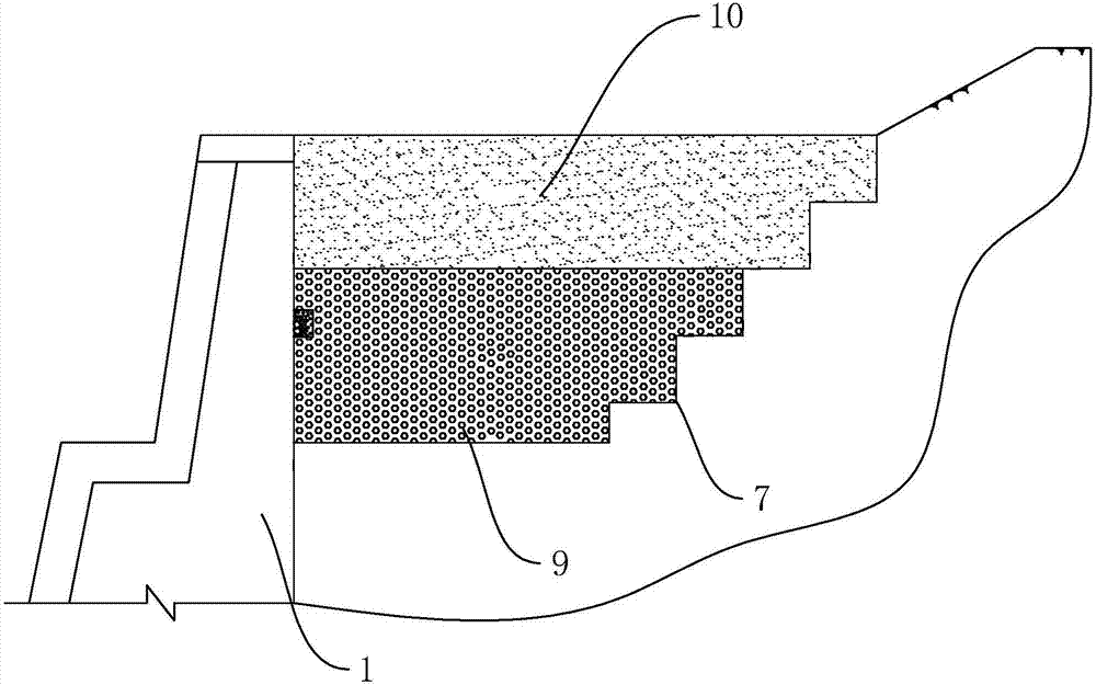
[0046] Firstly, fill the soil on the side of the wall 1 facing the water, cover the original river bottom scour line, and the top of the filled soil presents an inclined surface, and the height gradually decreases from the 1 position close to the wall to the 1 position away from the wall.

[0047] Drive into the prefabricated square pile 3 on the side of the body of wall 1 facing the water area, where the prefabricated square pile 3 is a detachable pile 32 . The prefabricated square pile 3 is close to the body of wall 1 and is vertical to the ground, and the end of the prefabricated square pile 3 away from the ground is higher than the surface formed by throwing and filling the soil.

[0048] Concrete wall body 4 is poured at prefabricated square pile 3, the side of concrete wall body 4 facing the water area is set as a vertical surface, the top surface of concrete wall bo...


PUM


Abstract

The invention discloses an approach channel retaining wall repairing method. According to the technical scheme, the approach channel retaining wall repairing structure comprises a wall which is arranged in a trapezoid shape; the wall comprises an upstream face arranged obliquely relative to the ground, and a downstream face vertical to the ground; prefabricated square piles vertical to the ground are arranged at the upstream face; a concrete wall body is poured on the sides, away from the ground, of the prefabricated square piles; the side, away from the wall, of the concrete wall body is provided with bagged gravels; the sides, away from the ground, of the bagged gravels are provided with a leveling layer covering the bagged gravels; and a backfill groove is dug in one side of the downstream face. Through the arrangement, the strength of the side of the upstream face is improved by arranging the bagged gravels; and after the backfill groove is dug in one side of the downstream face, the pressure borne by a soil matrix below the backfill groove is decreased. Through the measures, the pressure on the wall is reduced, the self-strength of the wall is improved, and accordingly, the probability that the wall collapses in the crack repairing process is decreased.

Description

technical field [0001] The invention relates to the field of water conservancy engineering port protection structures, in particular to a revetment repair structure for an approach channel and a method thereof. Background technique [0002] Bank revetment is a structure paved with stones or concrete on the river bank slope to protect the river bank. [0003] At present, the Chinese patent with the publication number CN201952776U discloses a revetment structure, which includes a base plate and a wall built on the base plate, the cross section of the wall is a right triangle, the front side of the wall is a straight side, and the rear side The upper part of the front side of the wall is made of strip stones, and the rest of the wall is made of mortar block stone. The back of the wall is backfill, and the top surface of the backfill is provided with a road. The road is composed of a stone pavement and stone curbs on both sides. A sand cushion and a gravel cushion are arranged ...

Claims


Application Information

Patent Timeline
IPC IPC(8): E02B3/16
CPCE02B3/16
Inventor 蒋锋
Owner 江苏省科佳工程设计有限公司
Why Eureka
Try Eureka