
Correcting tool and correcting method for rod length parameter of industrial robot

A technology of industrial robots and calibration methods, applied in the field of industrial robots, can solve the problems of positioning accuracy and repetition accuracy error, etc.

Inactive Publication Date: 2017-10-20
SHENZHEN HONGBAI TECH IND
View PDF8 Cites 3 Cited by
  • Summary
  • Abstract
  • Description
  • Claims
  • Application Information

AI Technical Summary

Problems solved by technology

[0007] The purpose of the present invention is to provide a correction method for the rod length parameters of an industrial robot, which can be used for the calculation and correction of the rod length parameters of a six-axis industrial robot, which solves the problem of the various components of a six-axis industrial robot in the process of production, manufacture, installation and use. The problem of positioning accuracy and repeatability error caused by the change of robot rod length

Method used


Image

  • Correcting tool and correcting method for rod length parameter of industrial robot
  • Correcting tool and correcting method for rod length parameter of industrial robot
  • Correcting tool and correcting method for rod length parameter of industrial robot

Examples


Embodiment 1

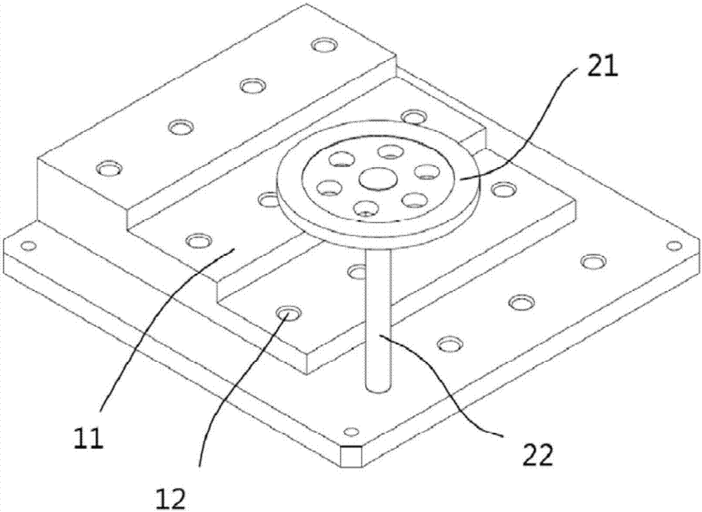
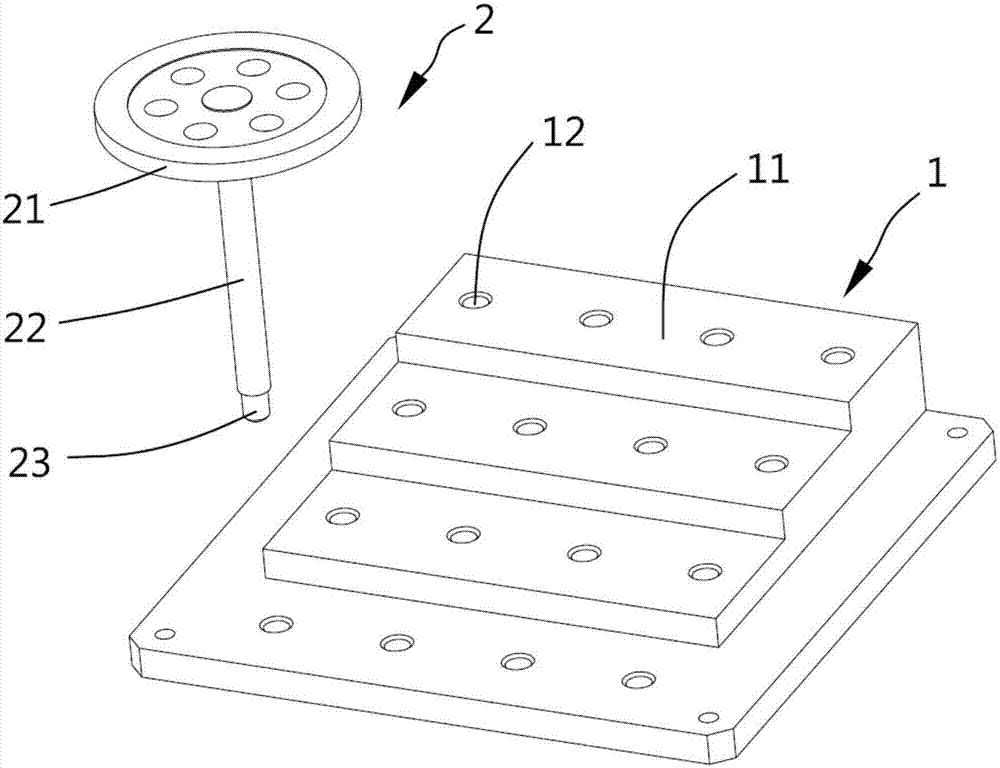
[0036] refer to figure 1 and figure 2 As shown, the present embodiment is a calibration tool for the rod length parameters of an industrial robot, including a step plate and a nail plate, and the step plate is provided with four steps of the same height, each layer is 10mm in height, and the length and width of the bottom layer are the same. 200mm, there are four round holes on each step, a total of 16, all the round holes form a 4×4 matrix arrangement, the distance between the round holes is 40mm, the diameter of the round holes is 8mm+0.1mm, the depth The diameter is 10mm, and the round hole is designed to match the thin rod of the nail plate. There are also four mounting screw holes at the four corners of the bottom layer.

[0037] The nail plate includes a flange part, a rod part and a thin rod part. The axis of the nail plate rod part coincides with the axis of the flange. The length of the rod is 100mm and the diameter is 10mm. On the end flange of an industrial robot...

Embodiment 2

[0039] This embodiment is a method for correcting the pole length parameters of an industrial robot. This method is implemented on the basis of the calibration tool in Embodiment 1. It measures the pole length of an industrial robot with six axes. It has six poles Long and six joints, the rods and joints are numbered from the side near the base in this embodiment.

[0040] The correction method includes the following steps:

[0041]S1. Install the step plate and the nail plate, and align the origin of the modeling of the industrial robot. When installing, one side of the outer edge of the step plate is perpendicular to the X axis of the world coordinate system of the industrial robot, and forms an angle of 30 degrees with the Y axis. , fix the flange part of the nail plate to the end flange of the industrial robot.

[0042] S2. Set up the system, including controlling the driver to enable the soft floating function, limiting the current amplitude, and allowing the tracking po...


PUM


Abstract

The invention relates to a correcting tool for a rod length parameter of an industrial robot. The correcting tool comprises a step plate and a nail disc. A plurality of same height steps are formed on the step plate; a plurality of round holes are formed in each step, and all the round holes are formed in a matrix; the nail disc comprises a flange portion and a rod portion, and the tail of the rod portion is processed into a slender rod portion matched with the round holes; in addition, the invention also relates to a correcting method for the rod length parameter of the industrial robot. The method is implemented based on the correcting tool. The method comprises the following steps of: S1, mounting the step plate and the nail disc and aligning a modeling original point for the industrial robot; S2, controlling the industrial robot, wherein the nail disc at the tail end moves to near one of the round holes of the step plate; S3, controlling the slender rod portion of the nail disc to fully enter the round hole, and recording the joint data in a current round hole position; S4, repeating the S2 and S3, successively correcting other round hole positions and recording corresponding joint data in the round hole positions; and S5, performing calculation by software to acquire a numerical value of actually measured rod length and correcting the numerical value to the rod length parameter of the industrial robot.

Description

technical field [0001] The invention belongs to the technical field of industrial robots, and relates to a method for correcting the rod length of an industrial robot and a calibration tool. The method can be applied to multiple processes such as research and development, testing, and on-site use of six-axis industrial robots. Background technique [0002] During the research and development process of industrial robots, due to the materials, manufacturing process, installation and other reasons of its components, the length of the rods of each joint of the industrial robot will change. However, when the robot performs trajectory control, it has been planning based on the theoretically modeled rod length of the industrial robot. Changes in the actual rod length will cause large errors in the positioning accuracy and repeatability of the industrial robot. [0003] In the process of industrial production, the change of the rod length will lead to poor product quality consisten...

Claims


Application Information

Patent Timeline
IPC IPC(8): B25J19/00G01B21/02
CPCB25J19/007G01B21/02
Inventor 张金泳韩沛文周靖蒋林李家波陈良军
Owner SHENZHEN HONGBAI TECH IND
Learn More