
Combined type vibrating sand making machine

A kind of sand making machine and composite technology, which is applied in the direction of solid separation, filter screen, grid, etc., can solve the problems of low crushing efficiency, unsmooth discharge, and insufficient material crushing of the sand making machine, and achieve good crushing effect, The structure is simple and the effect of ensuring uniformity

Pending Publication Date: 2017-10-20
尹国祥
View PDF0 Cites 15 Cited by
  • Summary
  • Abstract
  • Description
  • Claims
  • Application Information

AI Technical Summary

Problems solved by technology

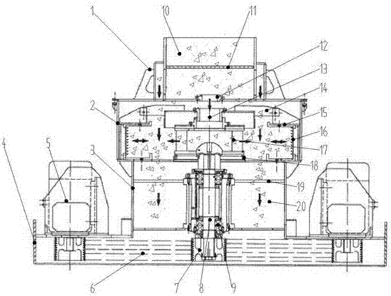
[0004] The purpose of the present invention is to provide a composite vibrating sand making machine in view of the above existing problems, which combines the vibrating screening with the crushing structure of the sand making machine, and can screen materials with uneven particle sizes to a certain extent. , and carry out the corresponding crushing action. The composite vibrating sand making machine of the present invention is also equipped with a material distribution component, which can realize the switching of various crushing forms and has a wide range of applications. Unsmooth, low crushing efficiency of sand making machine and insufficient crushing of materials greatly improve the crushing efficiency and quality of materials, and can also effectively improve the ore dressing efficiency of the whole ore beneficiation process

Method used


Image

  • Combined type vibrating sand making machine
  • Combined type vibrating sand making machine
  • Combined type vibrating sand making machine

Examples


Embodiment Construction

[0039] Below in conjunction with embodiment the present invention is described in detail.

[0040] In order to make the object, technical solution and advantages of the invention clearer, the present invention will be further described in detail below in conjunction with the examples. It should be understood that the specific embodiments described here are only used to explain the present invention, not to limit the present invention.

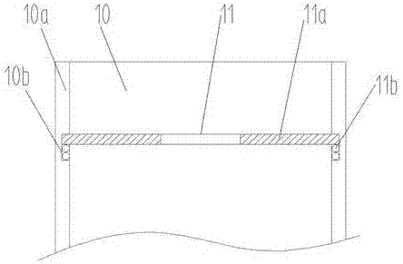
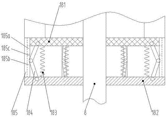
[0041] As shown in the accompanying drawings of the specification, a compound vibration sand making machine includes an upper chassis 1, a lower chassis 2, a discharge box 3 and a frame 4; the upper chassis 1, the lower chassis 2 and the discharge box 3 are respectively Corresponding to the feed port 10, the crushing cavity and the discharge port 20, the upper chassis 1, the lower chassis 2 and the discharge box 3 are connected sequentially on the axis from top to bottom, and the whole connection is connected with the lower frame 4; the frame ...


PUM


Abstract

The invention discloses a composite vibrating sand making machine, which comprises an upper machine case, a lower machine case, a discharge box and a frame, which respectively correspond to a material inlet, a crushing cavity and a material discharge port, and the three are in the order of axes from top to bottom connection, the connection is connected with the lower frame as a whole; the drive motor is connected to the frame, and the drive motor is connected to the rotating main shaft inside the sand making machine through the transmission mechanism, and the upper end is connected to the impeller; the main shaft of the rotating shaft is also connected with The vibrating mechanism cooperates with the impeller; the vibrating screening is combined with the crushing structure of the sand making machine, which can screen the materials with uneven particle size to a certain extent and perform corresponding crushing. There is also a material distribution component. It can realize the switching of various crushing forms and has a wide range of applications. Through the above structure, the problems of unsmooth discharge, low crushing efficiency of sand making machine and insufficient crushing of materials in the prior art can be effectively solved, and the crushing efficiency of materials is greatly improved. The quality and beneficiation efficiency of the beneficiation process.

Description

technical field [0001] The invention relates to the field of mining crushing and sand making equipment, in particular to a compound vibration sand making machine. Background technique [0002] Sand making machine is also called sand making machine, sand making machine and sand making machine. It is a special machine for producing sand and stone for construction. It is widely used in various ores, cement, refractory materials, aluminum where clinker, corundum, Glass raw materials, machine-made building stones and gold slag, especially for high-hard, extra-hard and wear-resistant materials such as silicon carbide, corundum, sintered bauxite, and beautiful sand, have higher output efficiency than other types of crushers. The sand making machine is suitable for crushing and shaping of soft or medium-hard and extremely hard materials. It is widely used in various ores, cement, refractory materials, aluminum where the clay clinker, corundum, glass raw materials, machine-made build...

Claims


Application Information

Patent Timeline
IPC IPC(8): B02C19/00B02C23/16B02C23/02B07B1/28B07B1/42B07B1/46
CPCB02C19/0018B02C19/005B02C23/02B02C23/16B02C2023/165B07B1/28B07B1/42B07B1/4609
Inventor 尹国祥
Owner 尹国祥
Learn More