


Quick Research
Generate reliable direction feasibility study reports for your R&D in just a few steps.

Technical Q&A
Discover and master advanced knowledge NOW. Basics, ideas, possibilities, all at once.

Find Solutions
As an expert in R&D theories, this can generate solutions to your technical problems instantly.

Evaluate Feasibility
Analyze your overall solution with one click, know your potential R&D risks in advance.

Monitor Landscape
Get weekly tech updates, stay abreast of the latest tech innovations and key insights.
Spraying-gun-installing-frame clothes wrapping roller in-out mechanism of roller-replaceable clothes wrapping machine
A technology of mounting frame and coating machine, which is applied in the direction of making medicines into special physical or ingestible devices, coatings, etc., and can solve the problem that the way the spray gun enters and exits the coating drum cannot be applied to replaceable drum coating machines, etc. problems, to achieve the effect of easy disassembly, avoid blocking, and reduce production costs
- Summary
- Abstract
- Description
- Claims
- Application Information
AI Technical Summary
Problems solved by technology
Method used
Image


Examples
specific Embodiment approach 1
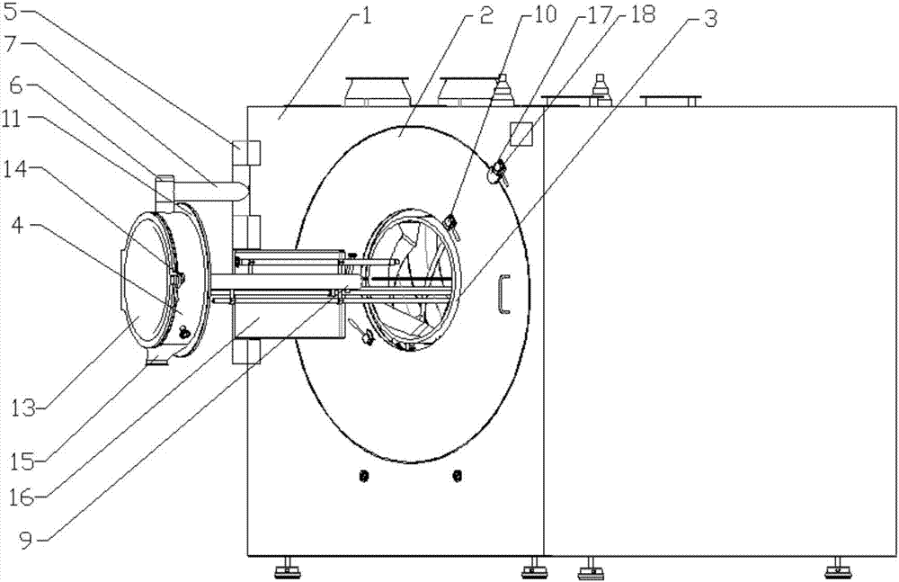
[0023] Specific implementation mode one: combine figure 1 , figure 2 , image 3 and Figure 4 Describe this embodiment, this embodiment includes the body 1 of the coating machine, and also includes the front door 2, the feed port 3, the front mouth ring 4, the first hinged base 5, the second hinged base 6, the first connecting rod 7, the support Rod 8 and spray gun mounting bracket 9, the front door 2 is installed on the front wall of the body 1, usually circular, the feed inlet 3 is opened on the front door 2, usually on the front wall of the front door 2 The center position, the size and position of the feed inlet 3 correspond to the size and position of the mouth of the coating drum located in the body 1, the front ring 4 is in the shape of a cylinder with two ends open, and the first A hinged base 5 is fixedly installed on one side of the front wall of the body 1, and the second hinged base 6 is fixedly installed on the outer wall of the front ring 4, usually on the ou...
specific Embodiment approach 2
[0026] Specific implementation mode two: combination Figure 4 To illustrate this embodiment, the first connecting rod 7, the second hinged base 6, the support rod 8 and the spray gun mounting frame 9 of this embodiment are hollow structures, forming the gas-liquid pipeline channel of the spray gun. The part of the front collar 4 connected to the second hinged base 6 may be provided with a through hole for the passage of gas and liquid pipelines. The gas-liquid pipeline of the spray gun in this embodiment can be placed in the channel of the hollow part of the first connecting rod 7, the second hinged base 6, the support rod 8 and the spray gun mounting frame 9, and the hidden line layout of this pipeline is more reasonable , to facilitate the disassembly, replacement, maintenance and cleaning of the spray gun mounting frame 9 and the spray gun installed on it, and also avoid the gas-liquid pipeline from blocking the spray path of the spray gun, thereby affecting the coating pr...
specific Embodiment approach 3
[0027] Specific implementation mode three: combination figure 1 , figure 2 , image 3 and Figure 4 Describe this embodiment, this embodiment also includes a first locking device 10, the rear end of the front ring 4 is provided with a first annular edge 11 extending radially outwards, and the outer wall of the front door 2 is provided with a The first locking device 10 matched with the first annular edge 11 . The first locking device 10 is generally a rotatable arc-shaped block, and a rotating handle is installed on the block. When the front ring 4 is turned to a position close to the front door 2, the Stopper, make it press on the front side wall of described first annular edge 11 and can realize the relative locking of described front ring 4 and front door 2, rotate described stopper under locking state, make it and The first annular edge 11 is staggered to realize the opening of the front collar 4 relative to the front door 2 . In order to ensure that the relative loc...
PUM
 Abstract
Description
Claims
Application Information
 - R&D Engineer
- R&D Manager
- IP Professional
- Industry Leading Data Capabilities
- Powerful AI technology
- Patent DNA Extraction
Browse by: Latest US Patents, China's latest patents, Technical Efficacy Thesaurus, Application Domain, Technology Topic, Popular Technical Reports.
© 2024 PatSnap. All rights reserved.Legal|Privacy policy|Modern Slavery Act Transparency Statement|Sitemap|About US| Contact US: help@patsnap.com