Pneumatic vehicle tyre

A technology for pneumatic tires and vehicles, applied in vehicle parts, tire parts, tire treads/tread patterns, etc., can solve problems such as damage to tire wet braking characteristics, and achieve roll-up prevention, low noise emission, and light tires. Effects of noise/lane noise

Active Publication Date: 2017-10-13
CONTINENTAL REIFEN DEUTSCHLAND GMBH
View PDF8 Cites 3 Cited by
  • Summary
  • Abstract
  • Description
  • Claims
  • Application Information

AI Technical Summary

Problems solved by technology

It is known that notch-like and therefore narrowly embodied grooves in the tread rib contribute to the generation of low rolling noise, but such grooves have the disadvantage that on the outer surface of the tread or rib The edge provided does not function to the desired extent, so that the wet braking properties of the tire are especially impaired

Method used


Image

  • Pneumatic vehicle tyre
  • Pneumatic vehicle tyre
  • Pneumatic vehicle tyre

Examples


Embodiment Construction

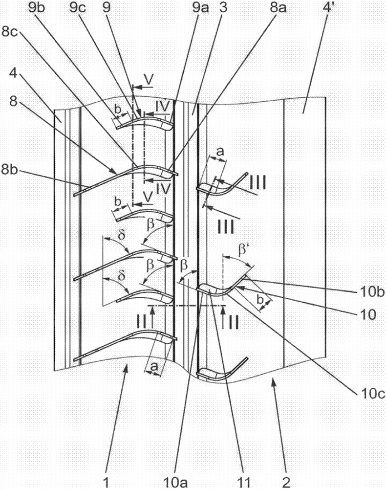
[0019] figure 1 A partial view of a tread embodied in accordance with the present invention is shown for a vehicle pneumatic tire, particularly for passenger cars, vans and similar vehicles. A circumferential section of two tread ribs 1 , 2 running around in the circumferential direction is shown, which are separated from one another by a wide circumferential groove 3 running around in the circumferential direction. The other circumferential grooves 4, 4' run laterally on the tread ribs 1, 2 respectively. In the embodiment shown, all circumferential grooves 3, 4, 4' run linearly in the circumferential direction with a constant width and a constant depth.

[0020] figure 2 A cross-section through the circumferential groove 3 separating the two ribs 1 , 2 from each other is shown. The circumferential groove 3 has a substantially U-shaped cross-section with a groove base 5, two groove sides 6 and 7, each with a groove base 5 and a groove side 6 and 7. 7 and one rounded trans...


PUM


Abstract

The invention relates to a pneumatic vehicle tyre having a tread which is divided by circumferential channels (3, 4) into profile positives which run in encircling fashion in a circumferential direction, wherein said profile positives include at least one profile rib (1, 2) which runs in encircling fashion in the circumferential direction and in which there run transverse channels (8, 9, 10), which transverse channels are formed parallel to one another in the manner of sipes and issue into at least one circumferential channel (3, 4) which delimits the profile rib (1, 2), and which transverse channels, at least in a section of the extent thereof close to the rib outer surface, are widened by way of a bevel (11, 12, 13). The transverse channels (8, 9, 10), which are formed in the manner of sipes, run in arcuate fashion relative to the circumferential channel (3, 4), wherein the bevels (11, 12, 13) are formed in each case on that channel flank (14b, 14'b, 14''b) of the transverse channels (8, 9, 10) which runs at the inner side of the arc, and wherein the transition region (6a, 7a) between that channel flank (6, 7) of the circumferential channel (3) into which the transverse channels (8, 9, 10), which are formed in the manner of sipes, issue and the outer surface of the profile rib (1, 2) is of rounded form.

Description

technical field [0001] The invention relates to a pneumatic vehicle tire having a tread which is divided by a plurality of circumferential grooves into a plurality of circumferentially encircling ribs, wherein at least one circumferentially encircling rib is subordinate to these Convex sipe, in which a plurality of transverse grooves formed parallel to each other, cut-like, run in the rib, these transverse grooves opening into at least one circumferential groove delimiting the rib and at least in its proximity to the rib The section of the extension of the outer surface has a chamfer at its grooved side. Background technique [0002] A pneumatic vehicle tire of the type mentioned at the outset is known, for example, from DE 10 2012 108 384 A1. The grooves formed in the form of incisions each have two groove sections running at an obtuse angle to each other and substantially rectilinearly, one of the groove sections running substantially in the tread transverse direction and...

Claims


Application Information

Patent Timeline
Patent Type & Authority Applications(China)
IPC IPC(8): B60C11/12B60C11/13
CPCB60C11/1281B60C11/0306B60C11/1323B60C11/1392B60C2011/0341B60C2011/036B60C2011/0372B60C2011/0386
Inventor 乌尔里希·贝尔
Owner CONTINENTAL REIFEN DEUTSCHLAND GMBH
Why Eureka
Try Eureka