
A Differential Structure Stabilized Platform Based on Flexible Cable Transmission

A technology with stable structure and differential mechanism, which is applied in the direction of navigation through speed/acceleration measurement, can solve problems such as poor adaptability, conflict between load capacity and lightweight requirements, and achieve large load capacity, strong adaptability, and guaranteed Effects of Transmission Accuracy and Stabilization Accuracy

Active Publication Date: 2019-10-15
NAT UNIV OF DEFENSE TECH
View PDF4 Cites 0 Cited by
  • Summary
  • Abstract
  • Description
  • Claims
  • Application Information

AI Technical Summary

Problems solved by technology

[0004] The technical problem to be solved by the present invention: In view of the conflict between the load capacity and lightweight requirements caused by the excessive load self-weight ratio of the existing two-axis two-frame integrated stable platform, and the lack of poor adaptability caused by the load layout mode, the platform's In the design, the flexible rope transmission mode is introduced, and the differential configuration is used to innovate the structural design to provide a platform that can effectively increase the load-to-weight ratio of the platform, and at the same time coordinate the contradiction between the precision requirements of the platform and the transmission characteristics of the mechanism, and solve the compact design of the platform and the improvement of adaptability Differential structure stabilization platform based on flexible cable transmission, with large load capacity, strong adaptability, light weight, high precision and compact structure

Method used


Image

  • A Differential Structure Stabilized Platform Based on Flexible Cable Transmission
  • A Differential Structure Stabilized Platform Based on Flexible Cable Transmission
  • A Differential Structure Stabilized Platform Based on Flexible Cable Transmission

Examples


Embodiment Construction

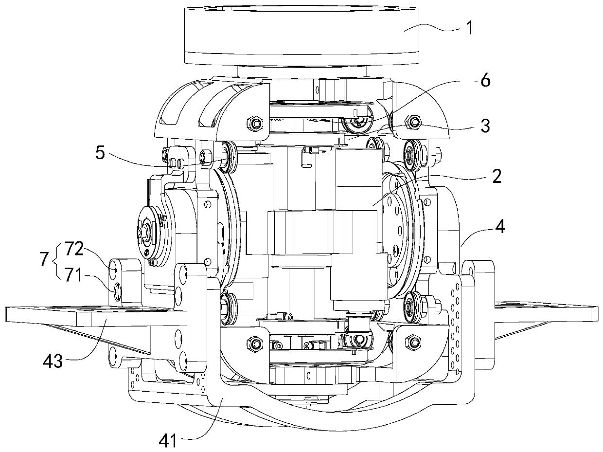
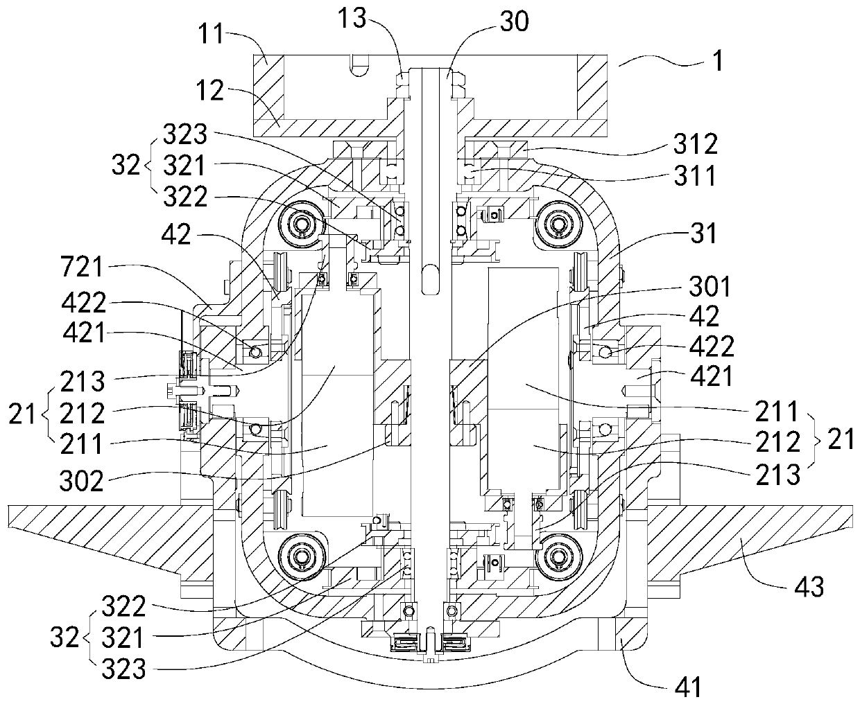
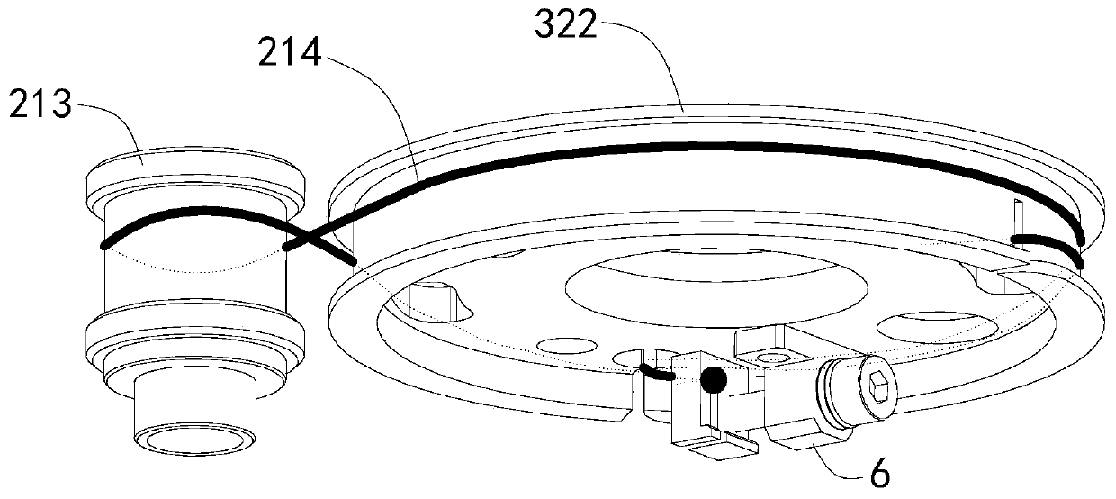
[0031] Such as figure 1 and figure 2 As shown, the stable platform of the differential structure based on flexible cable transmission in this embodiment includes a platform body 1, a drive unit 2, and a differential mechanism 5. The differential mechanism 5 includes an azimuth shafting system 3, a pitching shafting system 4, and a flexible cable assembly. The shafting system 3 and the pitching shafting system 4 are driven by a flexible cable assembly. The azimuth shafting system 3 is rotatably arranged on the platform body 1, and the pitching shafting system 4 is rotatably arranged on the azimuth shafting system 3 and is perpendicular to the axis of the azimuth shafting system 3. The output end of the drive unit 2 is in transmission connection with the azimuth shaft system 3 .

[0032] Such as figure 1As shown, a detection unit 7 is also provided on the azimuth axis system 3 and the pitch axis system 4. The detection unit 7 includes a gyro 71 and an encoder 72. The gyro 71 ...


PUM


Abstract

The invention discloses a stable platform with a differential structure based on flexible cable transmission. The stable platform comprises a platform body, a driving unit and a differential mechanism, wherein the differential mechanism comprises an azimuth axle, a pitching axle and a flexible cable component; the azimuth axle and the pitching axle are driven by the flexible cable component; the azimuth axle is rotationally arranged on the platform body; the pitching axle is rotationally arranged on the azimuth axle and is orthographic to the axis of the azimuth axle; and the output end of the driving unit is in driving connection with the azimuth axle. According to the stable platform disclosed by the invention, the limitation that a load weight ratio of an existing integral stable platform is difficult to increase can be broken, and high torque is outputted by a small motor; besides, higher transmission precision is ensured; the contradiction between precision requirements of the platform and transmission properties of the mechanism is effectively coordinated; the conflict between the compact design of the platform and improvement on adaptability is overcome; and the stable platform has the characteristics of high loading capacity, high adaptability, light weight, high precision and compact structure.

Description

technical field [0001] The invention relates to a two-degree-of-freedom stable platform for isolating carrier disturbance and stabilizing inertial pointing, and specifically relates to a differential structure stable platform based on flexible cable transmission. The type of load is suitable for but not limited to photoelectric detectors, and can be used for Various precision pointing mechanisms such as aircraft reconnaissance pods, ship-borne photoelectric tracking systems, and vehicle-mounted antenna systems. Background technique [0002] The stable platform is a precision pointing mechanism that compensates the carrier disturbance through multi-axis motion under the condition of the moving carrier, so as to keep the load pointing inertia stable and further realize other functions such as tracking the target. At present, in order to ensure high stability accuracy, the two-axis and two-frame integral stabilized platforms at home and abroad are often directly driven by torqu...

Claims


Application Information

Patent Timeline
Patent Type & Authority Patents(China)
IPC IPC(8): G01C21/18
Inventor 洪华杰李大泉张卫国侯军占江献良刘华谢馨原东阳
Owner NAT UNIV OF DEFENSE TECH
Learn More