Spherical wire walking robot and walking method thereof

A robot, spherical technology, applied in the direction of manipulators, motor vehicles, manufacturing tools, etc., can solve the problems of limiting mechanism adjustment ability, large space, limited swing range and swing speed of the rotating rod, etc., to achieve compact structure, small mechanism size, adaptability strong effect

Active Publication Date: 2017-10-13
GUILIN UNIV OF ELECTRONIC TECH
View PDF28 Cites 0 Cited by
  • Summary
  • Abstract
  • Description
  • Claims
  • Application Information

AI Technical Summary

Problems solved by technology

In order to achieve a better balance adjustment effect, the balance rotating rod of the wire walking robot must be able to generate a large enough adjustment torque, which can be achieved by increasing the moment of inertia of the swing rod. Therefore, the size of the rotating rod mechanism is often large, so its working It also requires a large space; at the same time, in order to avoid interference between the rotating rod mechanism and the steel wire rope, the swing range and swing speed of the rotating rod are usually very limited, thus limiting the adjustment ability of the mechanism
[0004] In addition, most of the current tightrope walking robots fail to take into account the anti-drop protection device, which greatly restricts the application of tightrope walking robots

Method used


Image

  • Spherical wire walking robot and walking method thereof
  • Spherical wire walking robot and walking method thereof
  • Spherical wire walking robot and walking method thereof

Examples


Embodiment Construction

[0031] The technical solutions of the present invention will be further described below in conjunction with the embodiments shown in the accompanying drawings.

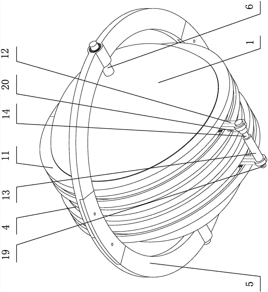
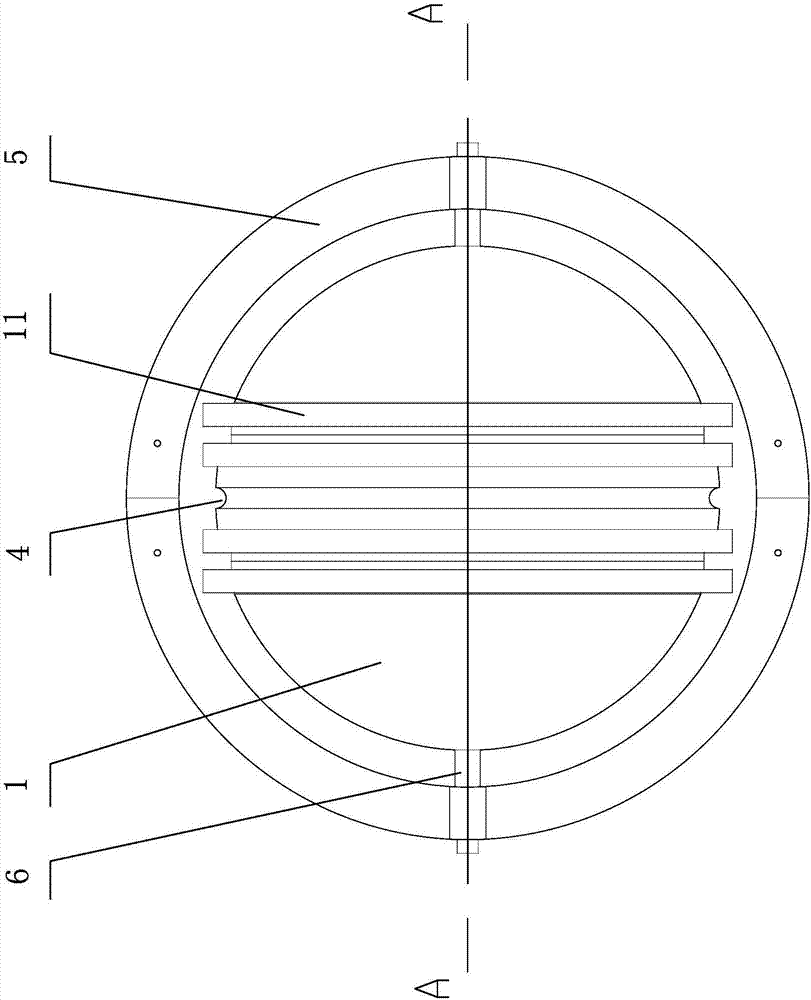
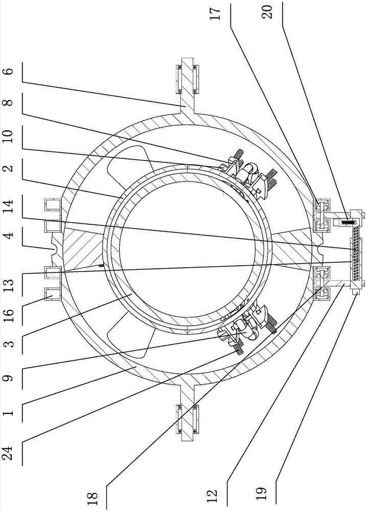
[0032] The spherical wire walking robot of the present invention has a structure comprising an outer spherical shell 1, a middle spherical shell 2 and an inner spherical shell 3 concentric with the center of the sphere, the inner spherical shell 3 has a larger moment of inertia as an inertial rotor, and the outer spherical shell 1 is placed in the horizontal ring frame 5, and the tops of the left and right hemispherical shells of the outer spherical shell 1 are respectively provided with horizontal left and right roller shafts 6, and the left and right roller shafts 6 are respectively installed on the ring frame 5 through bearing structures Above, the bearing structure is provided with an encoder that detects the rotation parameters of the ring frame 5 relative to the outer spherical shell 1; a semicircular groove 4 ( ...


PUM


Abstract

The invention discloses a spherical wire walking robot and a walking method of the spherical wire walking robot. The spherical wire walking robot comprises an outer spherical shell, a middle spherical shell and an inner spherical shell which share one sphere center. The outer spherical shell is arranged in a horizontal annular frame. A left half spherical shell body and a right half spherical shell body of the outer spherical shell are rotationally connected with the annular frame through a left roller shaft and a right roller shaft. The centers of the left half spherical shell body and the right half spherical shell body are concaved inwards to form an annular semi-circle groove. The outer spherical shell is connected with the middle spherical shell through a supporting column. An upper half spherical shell body and a lower half spherical shell body of the middle spherical shell are each provided with three omnidirectional wheels through wheel carriers. Each wheel carrier is provided with a motor and an encoder. The omnidirecitonal wheels enter the middle spherical shell and abut against the inner spherical shell. The left half spherical shell body and the right half spherical shell body on the two sides of the semi-circle groove are symmetrically provided with a left annular hanger frame and a right annular hanger frame. A locking device is perpendicularly hung to the bottoms of the left annular hanger frame and the right annular hanger frame for preventing falling. The whole mechanism is packaged in the spherical shells, the compactness is improved, an inertia rotor produces a resultant moment to adjust lateral balance of the mechanism and drive the mechanism to advance, and the control effect is good.

Description

technical field [0001] The invention relates to the balancing technology of a tightrope walking robot, in particular to a spherical tightrope walking robot and a walking method thereof. Background technique [0002] Tightrope walking robot is derived from using robot to simulate the behavior of human walking on a tightrope. It can automatically balance and walk on the top of the wire rope. It is mainly used in entertainment performances or high-voltage line deicing and other fields. [0003] Balance is the key problem that needs to be solved by the tightrope walking robot. Rotating the pendulum is an important way to adjust the lateral balance of the existing tightrope walking robot. The invention application with the patent number CN201510669449.1 discloses a "swing arm type single-wheel tightrope walking robot", which uses the left and right movement of the swing arm and the rotation of the swing rod to simulate the balance behavior of human walking on a tightrope. In ord...

Claims


Application Information

Patent Timeline
Patent Type & Authority Applications(China)
IPC IPC(8): B25J5/00B25J11/00B62D57/02
CPCB62D57/02B25J5/007B25J11/00
Inventor 黄用华王昌盛余记华庄未钟艳如黄美发孙永厚匡兵钟永全
Owner GUILIN UNIV OF ELECTRONIC TECH
Why Eureka
Try Eureka