Automatic clamping clamp for aerial rudder grinding machining

A grinding and automatic clamping technology, which is applied in the direction of grinding workpiece supports, etc., can solve the problems of low processing efficiency and accumulated processing errors

Active Publication Date: 2017-10-13
NANHUA UNIV
View PDF9 Cites 4 Cited by
  • Summary
  • Abstract
  • Description
  • Claims
  • Application Information

AI Technical Summary

Problems solved by technology

It solves the problem that two sets of fixtures are needed in the existing air rudder grinding process, and the processing efficiency is low due to two clamping alignments, and it is easy to accumulate processing errors.

Method used


Image

  • Automatic clamping clamp for aerial rudder grinding machining
  • Automatic clamping clamp for aerial rudder grinding machining
  • Automatic clamping clamp for aerial rudder grinding machining

Examples


Embodiment 1

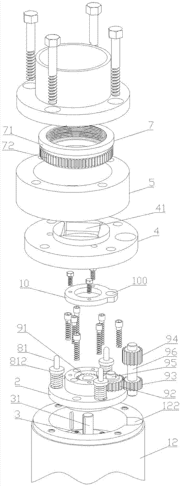
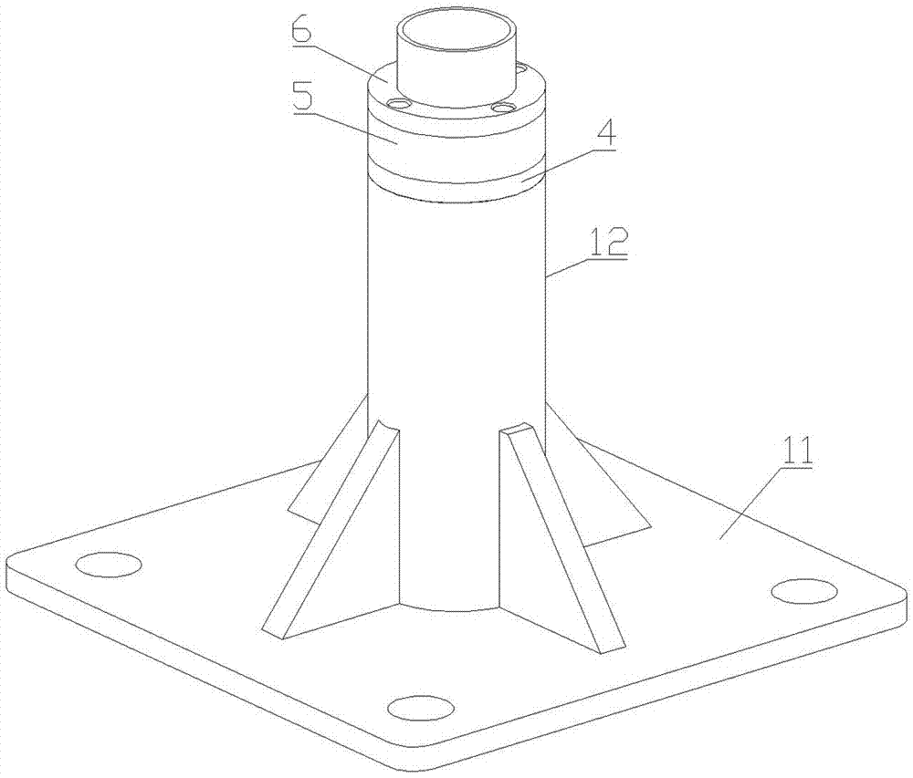
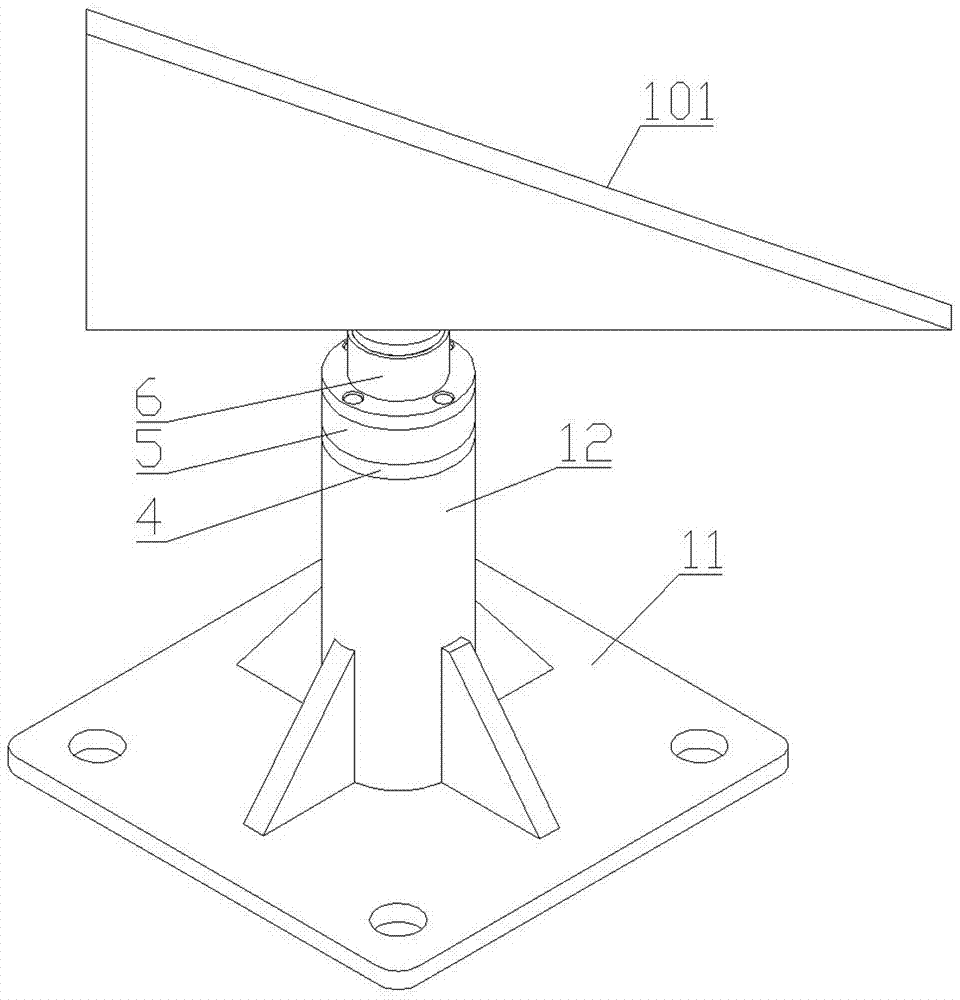
[0047] Such as Figure 1-13 As shown, the automatic clamping fixture for air rudder grinding includes a base, a step seat 2, a motor 3, an outer positioning cover 4, a sleeve 5, an inlet sleeve 6, a lock nut 7, an elastic push assembly, a transmission assembly and Position the cover 10 inside.

[0048] The base includes a bottom plate 11 and a motor seat 12 . The motor base 12 is in the shape of a sleeve and is vertically fixed on the upper end of the base plate 11. Its upper end is provided with a gear shaft hole B122, and a stepped hole 121 is provided in it. The end of the stepped hole 121 near the base plate 11 is a small-diameter section 1211, which is far away from the base plate. One end of 11 is a large-diameter section 1212, and a stepped surface 1213 is provided between the large-diameter section 1212 and the small-diameter section 1211. The large-diameter section 1212 of the stepped hole 121 forms an opening 1214 for the motor 3 to be installed at the upper end of ...


PUM


Abstract

The invention relates to an automatic clamping clamp for aerial rudder grinding machining. The automatic clamping clamp comprises a base, a step base, a motor, an outer positioning cover, a sleeve, an inlet sleeve, a locking nut, an elasticity pushing assembly and a transmission assembly; the base comprises a base plate and a motor base; the step base is fixedly installed on the motor base, and a center hole is formed in the step base; the motor is installed in a step hole of the motor base and is fixedly connected with the step base; the outer positioning cover is fixedly connected to the position of an opening in the upper end of the motor base, and a square hole is formed in the center position of the outer positioning cover; the sleeve is fixedly connected to the upper end of the outer positioning cover; the inlet sleeve is fixedly connected to the upper end of the sleeve; the locking nut is movably installed in the inner hole of the sleeve, the lower end of the locking nut is supported and borne by the elasticity pushing assembly, a contact face is arranged at the upper end of the outer wall of the locking nut, and a transmission structure is arranged at the lower end of the outer wall of the locking nut; the lower end of the elasticity pushing assembly is related to the step base, the upper end of the elasticity pushing assembly extends into the inner hole of the sleeve to be in contact with the lower end face of the locking nut, and therefore elastic bearing is provided for the locking nut; and the transmission assembly is arranged between the motor and the locking nut, and is used for transmitting power of the motor to the locking nut.

Description

technical field [0001] The invention relates to a fixture, in particular to an automatic clamping fixture for air rudder grinding. Background technique [0002] The air rudder is the direction control part on the missile, which is used to control the flight attitude and flight trajectory of the missile. Its structure is as Figure 4 As shown, it includes a triangular plate 101, a frustum 102, a threaded rod 103 and a square block 104; the front end face and the rear end face of the triangular plate 101 are right-angled triangles, and the front and rear end faces are connected by the bottom face, the left side and the right side; One end of the frustum 102 with a large diameter is connected to the bottom surface of the triangular plate 101; one end of the threaded rod 103 is connected to the end surface of the small diameter end of the frustum 102, and a square block 104 is connected to the end surface of the other end. [0003] The bottom surface and the left side of the ai...

Claims


Application Information

Patent Timeline
Patent Type & Authority Applications(China)
IPC IPC(8): B24B41/06
CPCB24B41/06
Inventor 唐德文张家雨何彬彭聪谢宇鹏
Owner NANHUA UNIV
Why Eureka
Try Eureka