
Large-amplitude high repetition frequency nanosecond balance pulse signal generator

A technology of signal generator and balanced pulse, which is applied in the direction of electric pulse generator circuit, energy storage element to generate pulse, instrument, etc., can solve the problem that it is difficult to meet the actual detection application requirements of ultra-wideband radar system, the repetition frequency of output pulse signal is not high, Problems such as low output pulse amplitude, to achieve the effect of novel design, steep pulse front, and small trailing oscillation

Pending Publication Date: 2017-10-10
TECH & ENG CENT FOR SPACE UTILIZATION CHINESE ACAD OF SCI
View PDF5 Cites 5 Cited by
  • Summary
  • Abstract
  • Description
  • Claims
  • Application Information

AI Technical Summary

Problems solved by technology

[0003] In the prior art, conventional cmos devices are used to design and generate pulse signals. This pulse signal output method has the following disadvantages: the output pulse amplitude is low, and the repetition frequency of the output pulse signal is usually not high due to the limitation of the device. Therefore, it is difficult to meet the super Practical Detection Application Requirements for Wideband Radar Systems

Method used


Image

  • Large-amplitude high repetition frequency nanosecond balance pulse signal generator
  • Large-amplitude high repetition frequency nanosecond balance pulse signal generator

Examples


Embodiment Construction

[0031] In order to make the object, technical solution and advantages of the present invention clearer, the present invention will be described in further detail below in conjunction with specific embodiments and with reference to the accompanying drawings. Implementations not shown or described in the accompanying drawings are forms known to those of ordinary skill in the art. Additionally, while illustrations of parameters including particular values ​​may be provided herein, it should be understood that the parameters need not be exactly equal to the corresponding values, but rather may approximate the corresponding values ​​within acceptable error margins or design constraints. The directional terms mentioned in the embodiments, such as "upper", "lower", "front", "rear", "left", "right", etc., are only referring to the directions of the drawings. Therefore, the directional terms used are for illustration and not for limiting the protection scope of the present invention. ...


PUM


Abstract

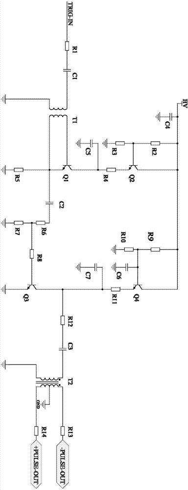
The invention provides a large-amplitude high repetition frequency nanosecond balance pulse signal generator. The large-amplitude high repetition frequency nanosecond balance pulse signal generator includes a unipolarity pulse signal generation circuit and a balance pulse generation circuit, wherein the unipolarity pulse signal generation circuit includes a triode pulse generation circuit which is formed by triodes; each triode includes two cascades, has a cascaded connection design, and has avalanche effect; the unipolarity pulse signal generation circuit is used for generating a large-amplitude high repetition frequency nanosecond negative pulse signal, started by the input bipolarity start pulse signal; the front end of the balance pulse generation circuit is electrically connected with the unipolarity pulse signal generation circuit; and the balance pulse generation circuit is used for converting the large-amplitude high repetition frequency nanosecond negative pulse signal into a balance pulse signal, and generating a large-amplitude nanosecond balance pulse signal. The large-amplitude high repetition frequency nanosecond balance pulse signal generator has the advantages of being novel in design, being simple in the circuit structure, being high in the waveform symmetry of the generated nanosecond balance pulse signal, being low in the ringing level, being high in amplitude, and being high in repetition frequency, and being able to be applied to a pulse ultra wide band radar system to guarantee greater detection distance and good detection performance.

Description

technical field [0001] The invention belongs to the technical field of electronic components in the electronics industry, and in particular relates to a nanosecond balanced pulse signal generator with large amplitude and high repetition frequency. Background technique [0002] UWB technology uses nanosecond or picosecond impulse pulses as carriers to transmit information. It has the advantages of high bandwidth, low power consumption, strong anti-multipath fading ability, and good concealment performance. It can be widely used in radio communications, ultra- Broadband radar system detection, positioning and tracking and other fields. In order to achieve a large distance detection, the transmitted pulse signal is required to have a large instantaneous power, that is, a large pulse amplitude is required. At the same time, in order to meet the ultra-wideband detection requirements, a narrow pulse width and a high repetition frequency are required. Therefore, how to generate a l...

Claims


Application Information

Patent Timeline
Patent Type & Authority Applications(China)
IPC IPC(8): H03K3/57G01S7/282
CPCH03K3/57G01S7/282
Inventor 管洪飞夏新凡吕宏宇王亦风张璐郭林张群英
Owner TECH & ENG CENT FOR SPACE UTILIZATION CHINESE ACAD OF SCI
Learn More