Projection display equipment for vehicles
A projection display and vehicle technology, applied in vehicle components, static indicators, instruments, etc., can solve problems such as reducing display quality, and achieve the effect of improving display quality and suppressing the increase in quantity
- Summary
- Abstract
- Description
- Claims
- Application Information
AI Technical Summary
Problems solved by technology
Method used
Image
Examples
Deformed example 1
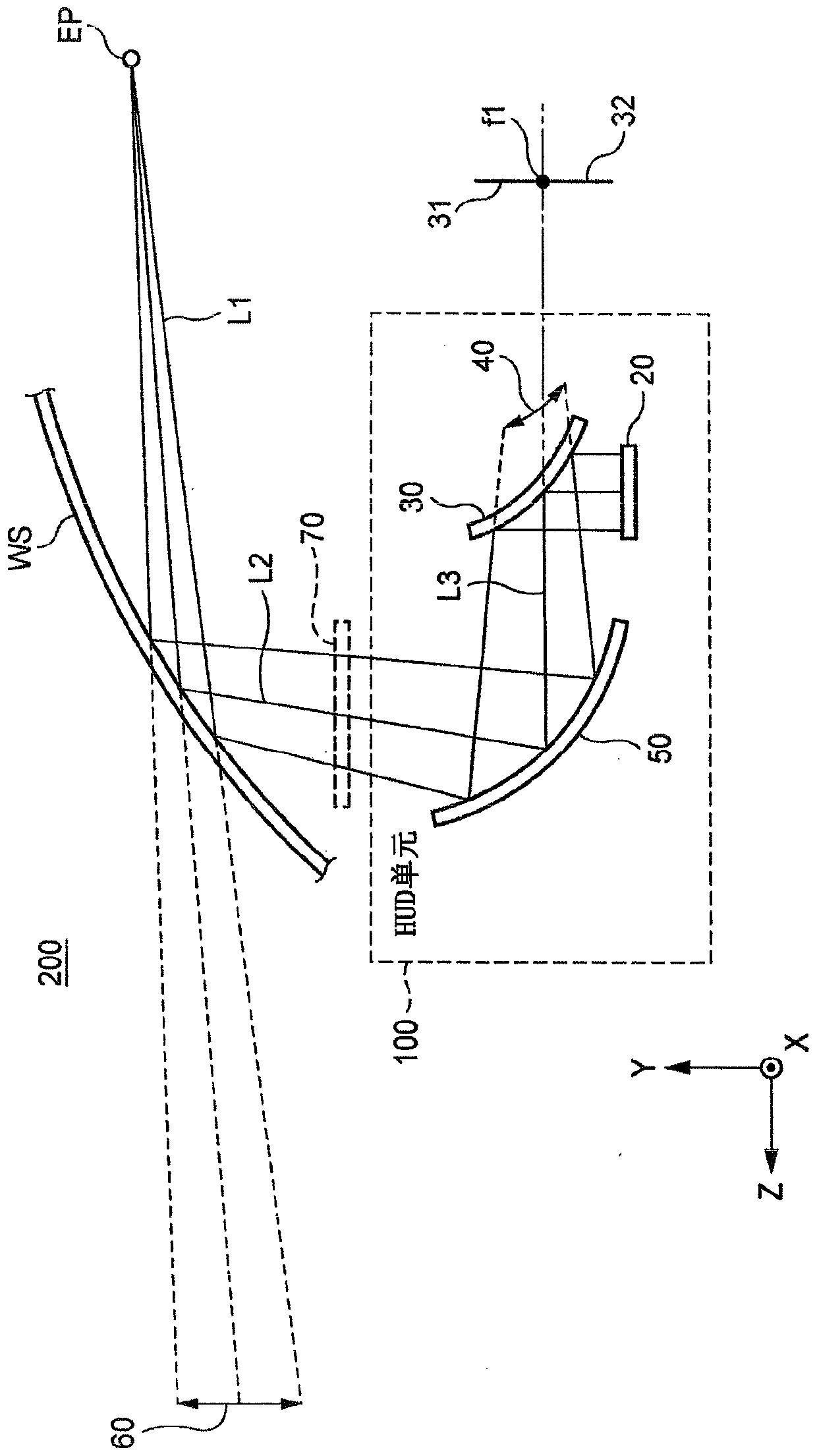
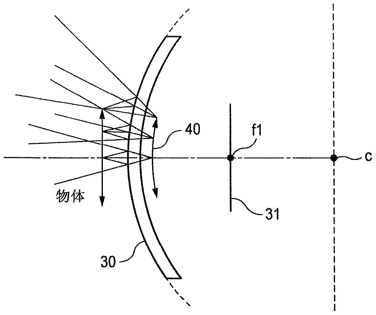
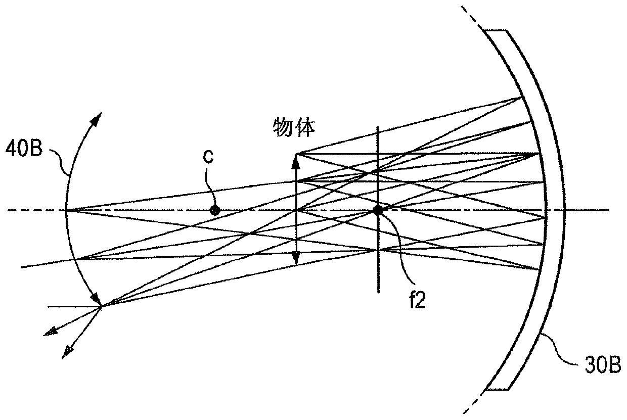
[0072] image 3 The positional relationship among the concave mirror 30B, the object, and the intermediate image to be used in Modification 1 is shown. That is, in Modification 1, using image 3 The concave mirror 30B shown in place of figure 1 Convex mirror 30 is shown.
[0073] Also, in Modification 1, the optical path is formed such that the image 3 The display device 20 corresponding to the shown "object" is disposed at a position farther from the reflective surface of the concave mirror 30B than the focal plane, which includes the focal point f2 of the concave mirror 30B, as image 3 shown. image 3 Point c in represents the spherical center of the reflecting surface of the convex mirror 30B.
[0074] In modification 1, such as image 3 As shown, the intermediate image 40B is formed as a real image at a position farther from the reflective surface of the concave mirror 30B than the focal point f2 of the concave mirror 30B. The beam of intermediate image 40B, i.e.,...
Deformed example 2
[0078] Figure 4 The positional relationship between the convex lens 30C, the object, and the intermediate image to be used in Modification 2 is shown. also, Figure 5 An optical path of a projection display device for a vehicle according to Modification 2 is shown.
[0079] That is, in Modification 2, using Figure 4 The convex lens 30C shown in place of figure 1 shown in the convex mirror 30, and as Figure 5 The light path is formed as shown. Both faces of the convex lens 30C may have a convex shape, or only one face thereof may have a convex shape and the other face may have a planar shape.
[0080] Also, in Modification 2, the optical path is as Figure 5 formed as shown such that with Figure 4 The display device 20 corresponding to the shown "object" is disposed at a position farther from the convex lens 30C than the focal plane including the focal point f3a of the convex lens 30C, as shown in Figure 4 shown.
[0081] In modification 2, such as Figure 4 As s...
PUM
 Abstract
Description
Claims
Application Information
 - Generate Ideas
- Intellectual Property
- Life Sciences
- Materials
- Tech Scout
- Unparalleled Data Quality
- Higher Quality Content
- 60% Fewer Hallucinations
Browse by: Latest US Patents, China's latest patents, Technical Efficacy Thesaurus, Application Domain, Technology Topic, Popular Technical Reports.
© 2025 PatSnap. All rights reserved.Legal|Privacy policy|Modern Slavery Act Transparency Statement|Sitemap|About US| Contact US: help@patsnap.com


