
Cooling device for computer room

A computer room and heat dissipation device technology, applied in household heating, heating methods, household heating, etc., can solve the problems of polluting the internal air of the computer room, poor external air quality, polluting the air of the computer room, etc., and achieve enhanced heat dissipation effect and structure Simple, energy-saving effect

Inactive Publication Date: 2017-10-10
合肥锦和信息技术有限公司
View PDF2 Cites 0 Cited by
  • Summary
  • Abstract
  • Description
  • Claims
  • Application Information

AI Technical Summary

Problems solved by technology

In order to ensure the stable operation of the equipment in the computer room, the air conditioner needs to work all the time. Even when the outside temperature is relatively low, because the computer room is isolated from the outside world, the air conditioner in the computer room still needs to run, which is obviously not energy-saving enough.
If the outside air is introduced, it may pollute the air inside the equipment room due to the low quality of the outside air (such as high dust, etc.), affecting the operation of the equipment
[0004] In the patent document with the publication number CN205822853U, a rapid heat dissipation machine room is disclosed. The rapid heat dissipation machine room includes a main body of the machine room. The lower side of the lower side and the lower side of the second side wall are respectively provided with a plurality of first ventilation devices, and the roof is provided with a second ventilation device. The second ventilation device includes an air duct and a filter screen arranged on the top of the air duct. A fan, this utility model realizes rapid heat exchange in the machine room. This heat exchange method can be used for spring, autumn and winter when the outside temperature is low, and at night in general summer, so as to save the power consumption of the refrigeration device and overcome the dead angle of ventilation in the machine room. However, the utility model still adopts the traditional ventilation heat dissipation method, which may pollute the air inside the computer room and affect the operation of the equipment

Method used


Image

  • Cooling device for computer room
  • Cooling device for computer room
  • Cooling device for computer room

Examples


Embodiment 1

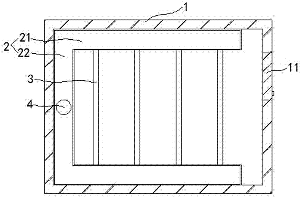
[0029] Such as Figure 1~3 Shown is a cooling device for a computer room in this embodiment, which includes a computer room body 1. A water tank 2 is provided in the machine room body 1. The water tank 2 is concave and attached to the wall of the computer room body 1. The water tank 2 includes two parallel to each other. slot 21 and a connecting slot 22, a plurality of thin slots 3 are connected between the two parallel slots 21 parallel to each other, computer cabinets are installed above the plurality of thin slots 3; a water inlet pipe 4 is connected above the connecting slot 22 And there is an outlet pipe 5 below.

[0030] Through the water in the water tank 2 and the thin groove 3, the water in the machine room is cooled and dissipated, energy is saved, and the heat dissipation effect is good. The thin groove 3 is located under the computer cabinet and has a better heat dissipation effect; The external water pipelines are connected to provide water for the machine room, ...

Embodiment 2

[0048] Such as figure 1 , image 3 , Figure 4As shown, a heat dissipation device for a computer room in this embodiment includes a computer room body 1, and a water tank 2 is arranged in the machine room body 1. The water tank 2 is concave and attached to the wall of the computer room body 1. The water tank 2 includes two parallel to each other. slot 21 and a connecting slot 22, a plurality of thin slots 3 are connected between the two parallel slots 21 parallel to each other, computer cabinets are installed above the plurality of thin slots 3; a water inlet pipe 4 is connected above the connecting slot 22 And there is an outlet pipe 5 below.

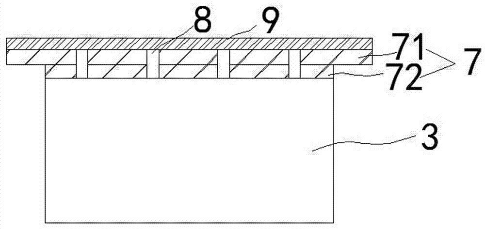
[0049] In this embodiment, a first dust cover 6 is provided above the water tank 2 , and a second dust cover 7 is provided above any narrow slot 3 .

[0050] In this embodiment, the first dust cover 6 and the second dust cover 7 are made of stainless steel and coated with anti-rust paint.

[0051] In this embodiment, the second dus...


PUM


Abstract

The invention discloses a cooling device for a computer room, and relates to the technical field of computer room equipment. The cooling device for the computer room comprises a computer room body. A water channel is formed in the computer room body. The water channel is in a U shape and is arranged attached to the wall of the computer room body. The water channel comprises two parallel grooves which are parallel to each other and a connecting groove. A plurality of fine grooves are connected between the two parallel grooves parallel to each other. A computer cabinet is installed above the multiple fine grooves. The upper side of the connecting groove communicates with a water inlet pipe, and the lower side of the connecting groove communicates with a water outlet pipe. The cooling device for the computer room is simple in structure, low in cost and convenient to install; and a pleasantly cool environment inside the computer room can be effectively guaranteed in a water cooling mode, and computers can be effectively cooled.

Description

technical field [0001] The invention belongs to the technical field of computer room equipment, and in particular relates to a cooling device for a computer room. Background technique [0002] The computer room project refers to the basic project designed and configured to ensure the safe, stable and reliable operation of the key equipment and devices in the computer room (also known as the data center). Data information security provides a guarantee environment, but also creates a healthy and suitable working environment for the staff. [0003] In the computer room project, the computer room usually requires a good heat insulation effect to prevent the change of the external environment temperature from affecting the temperature in the computer room, so that the temperature inside the computer room is relatively constant, and the temperature in the computer room is generally adjusted by the air conditioner or ventilation system control. In order to ensure the stable opera...

Claims


Application Information

Patent Timeline
Patent Type & Authority Applications(China)
IPC IPC(8): F24F5/00F24F11/00F24F13/28
CPCF24F5/0003F24F5/0017F24F13/28Y02E60/14
Inventor 不公告发明人
Owner 合肥锦和信息技术有限公司
Learn More