Dust collector motor and motor

A technology of vacuum cleaners and brushes, which is applied in the direction of electrical components, electromechanical devices, electric components, etc., can solve problems affecting the service life of motors, and achieve the effects of optimizing iron core design, avoiding air leakage problems, reducing cross-sectional size and volume

Pending Publication Date: 2017-10-03
AMETEK IND TECH SHANGHAI CO LTD
View PDF4 Cites 3 Cited by
  • Summary
  • Abstract
  • Description
  • Claims
  • Application Information

AI Technical Summary

Problems solved by technology

In actual use, the motor is usually installed in a relatively closed space, if the heat genera...

Method used


Image

  • Dust collector motor and motor
  • Dust collector motor and motor
  • Dust collector motor and motor

Examples


Embodiment Construction

[0070] The present invention is described in detail below in conjunction with accompanying drawing:

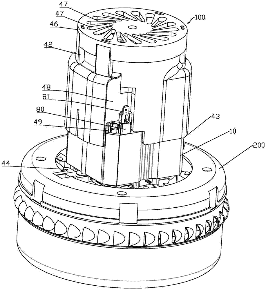
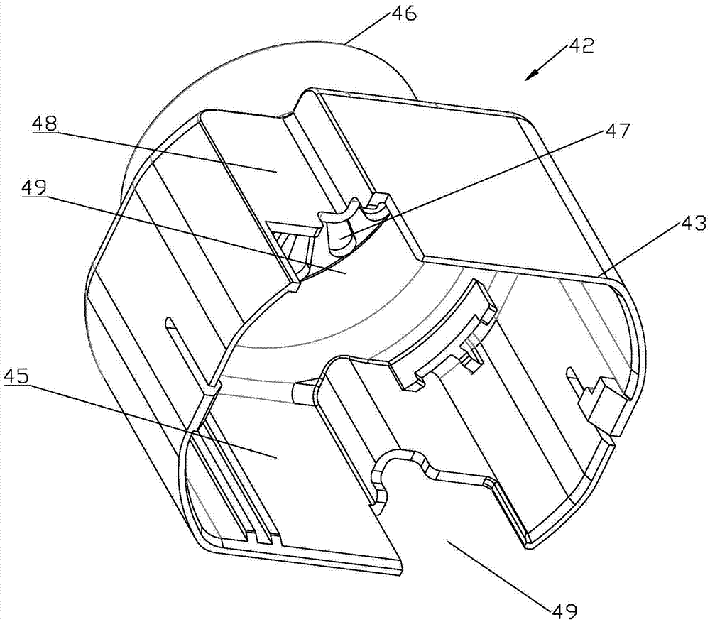
[0071] Such as figure 1 , figure 2 , image 3 and Figure 4 As shown, the motor 100 includes a stator core 10, a stator core winding 20, a rotor core 30 and a fan. The stator core 10 is formed by stacking a plurality of silicon steel sheets in sequence. The stator core 10 has an upper surface 11 and a lower surface (not shown). The lower surface is a surface opposite to the upper surface 11 . Both the upper surface 11 and the lower surface are cross sections of the stator core 10 . The stator core 10 has a first through hole 13 . The rotor core 30 passes through the first through hole 13 of the stator core 10, and the rotor core 30 is rotatably disposed. The stator core winding 20 is disposed in the first through hole 13 of the stator core 10 . The stator core windings 20 are all located in the first through hole 13 , or partially protrude from the stator core 10 alo...


PUM

PropertyMeasurementUnit
Perimeteraaaaaaaaaa
Heightaaaaaaaaaa
Poweraaaaaaaaaa

Abstract

The invention discloses a dust collector motor and a motor. The dust collector motor comprises a stator core, a stator core winding, a rotor core and a cooling fan, wherein the stator core is provided with a first through hole; the stator core winding is arranged in the first through hole partially or totally; the rotor core penetrates through the first through hole and is rotatably arranged; the cooling fan comprises a fan blade and a fan housing; the fan housing is a cylinder whose first end is open, the fan housing is provided with a cylinder cavity and an air inlet is arranged in a second end of the fan housing; the fan blade is arranged in the cylinder cavity of the fan housing and sleeves the end of the rotor core, and the rotor core drives the fan blade to rotate; the second end of the fan hosing sleeves the outer surface of the stator core. Compared with the existing motor with the same vacuum suction and the same power, the cross sectional area of the stator core of the motor in the invention is reduced by 36% at most, and the volume is reduced by 8% at most.

Description

technical field [0001] The invention specifically relates to a vacuum cleaner motor and the motor. Background technique [0002] The vacuum cleaner motor is the power source of the vacuum cleaner. For vacuum cleaner users, they always hope to use products with smaller volume and higher power. The requirement of the vacuum cleaner motor in this field is how to reduce the volume of the motor and reduce the space it occupies. However, the motors used in vacuum cleaners in the prior art have a relatively high technical maturity, and it is extremely difficult to make any changes to them. Especially when reducing the size of the motor, the heat generated by the winding is higher for the same power. In actual use, the motor is usually installed in a relatively closed space. If the heat generated by the motor cannot be dissipated in time, the service life of the motor will be seriously affected. For motor manufacturers, reducing the size of the motor is not only related to produ...

Claims


Application Information

Patent Timeline
IPC IPC(8): H02K9/06H02K5/14H02K9/28H02K3/50
CPCH02K3/521H02K5/145H02K9/06H02K9/28H02K2213/03
Inventor 徐安生金伟夏南尤杰
Owner AMETEK IND TECH SHANGHAI CO LTD
Why Eureka
Try Eureka