Single flow reducer tube wound heat exchanger

A technology of coiled heat exchangers and different-diameter tubes, which is applied in the direction of indirect heat exchangers, heat exchanger types, heat exchanger shells, etc., can solve the problem of insufficient shell-side fluid turbulence, large convective heat transfer coefficient, and The problem of small convective heat transfer coefficient can achieve the effect of enhancing the convective heat transfer effect in the tube and the comprehensive heat transfer effect of the heat exchanger, reducing the flow resistance and reducing the diameter of the core tube

Active Publication Date: 2019-08-30
LUOYANG LONGHUI PETROCHEM ENG
View PDF6 Cites 0 Cited by
  • Summary
  • Abstract
  • Description
  • Claims
  • Application Information

AI Technical Summary

Problems solved by technology

However, in the existing coiled tube heat exchanger, the fluid in the spiral heat exchange tube is a helical flow or has a phase change, so the convective heat transfer coefficient in the tube is relatively large; while the adjacent inner and outer coils in the shell side are supported by pads, The heat exchange tubes in the same layer are closely arranged, so the turbulent effect of the shell-side fluid is insufficient, and the convective heat transfer coefficient is small

Method used


Image

  • Single flow reducer tube wound heat exchanger
  • Single flow reducer tube wound heat exchanger
  • Single flow reducer tube wound heat exchanger

Examples


Embodiment Construction

[0012] The present invention will be further described below with reference to the accompanying drawings.

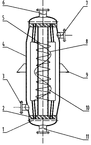
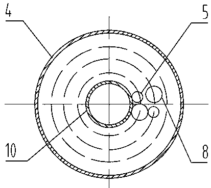
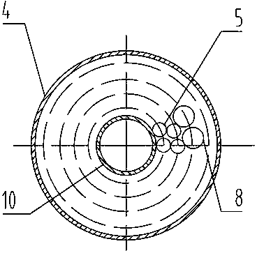
[0013] The assembly process of the single-flow reducer wound tube heat exchanger: First, the core tube and the tube sheets at both ends are welded and fixed, and the core tube is located at the center of the tube sheets at both ends. Then, for the first winding arrangement, First, insert one end of the small-diameter winding tube and the large-diameter winding tube into the same tube sheet adjacently, and weld and fix the core tube with a tube clip, and then alternately wind the core tube in the same layer according to the designed helix angle. The other end of the tube is inserted into another tube sheet adjacently; for the second type of winding arrangement, the first end of the small-diameter winding tube is inserted into the inner area of ​​a tube sheet, and the tube is welded and fixed with the core tube. , wind several layers of small-diameter winding tubes on the ...


PUM


Abstract

The invention discloses a single-stream coiled tubular heat exchanger with tubes of different diameters. The single-stream coiled tubular heat exchanger with the tubes of the different diameters comprises channels, a shell body, tube plates, a core cylinder, small-diameter coiled tubes, large-diameter coiled tubes, positioning strips, a shell pass inlet tube, a shell pass outlet tube, a tube pass inlet tube, a tube pass outlet tube and lug type supporting seats. The single-stream coiled tubular heat exchanger with the tubes of the different diameters is characterized in that the two kinds of structures of the small-diameter coiled tubes and the large-diameter coiled tubes are coiled outside the core cylinder and can be arranged in two modes, the first mode is that each layer of coiled tube is formed by alternatively coiling of the small-diameter coiled tube and the large-diameter coiled tube, and the second mode is that a plurality of internal layers are formed by coiling of the small-diameter coiled tubes and a plurality of external layers are formed by coiling of the large-diameter coiled tubes; and the adjacent internal and external layers of coiled tubes are the same in winding mode and spiral angle but opposite in coiling direction, and directly make contact with each other, the axial spacing of coiled tubes in the same layer is positioned by using the positioning strips, and the two tube heads of the small-diameter coiled tubes and the large-diameter coiled tubes are arranged on the tube plates of the two ends correspondingly and alternatively. According to the single-stream coiled tubular heat exchanger with the tubes of the different diameters, the two coiling modes of the small-diameter coiled tubes and the large-diameter coiled tubes are adopted, the heat exchanging area and the gaps between the coiled tube layers are enlarged, and the heat exchanging effect of shell pass fluid is enhanced.

Description

technical field [0001] The invention relates to the technical field of shell-and-tube heat exchangers, in particular to a single-stream reducing tube-wound heat exchanger. Background technique [0002] Heat exchanger is an important unit equipment in many industrial productions such as chemical industry, oil refining, power, metallurgy, etc. The wound tube heat exchanger is a shell-and-tube heat exchanger with a special structure, which mainly includes parts such as shell, core tube and winding tube; its basic structure is that the winding tube is wound on the outside of the core tube, and the core tube is located in the heat exchange At the central axis of the shell side of the device, it is used as a support for the winding tube bundle. [0003] Compared with other tubular heat exchangers, coiled tube heat exchangers have attracted widespread attention due to their compact structure and good heat exchange effect. However, in the existing coiled tube heat exchanger, the f...

Claims


Application Information

Patent Timeline
Patent Type & Authority Patents(China)
IPC IPC(8): F28D7/02F28F9/02
Inventor 吴金星王蕾赵进元
Owner LUOYANG LONGHUI PETROCHEM ENG
Why Eureka
Try Eureka