


Quick Research
Generate reliable direction feasibility study reports for your R&D in just a few steps.

Technical Q&A
Discover and master advanced knowledge NOW. Basics, ideas, possibilities, all at once.

Find Solutions
As an expert in R&D theories, this can generate solutions to your technical problems instantly.

Evaluate Feasibility
Analyze your overall solution with one click, know your potential R&D risks in advance.

Monitor Landscape
Get weekly tech updates, stay abreast of the latest tech innovations and key insights.
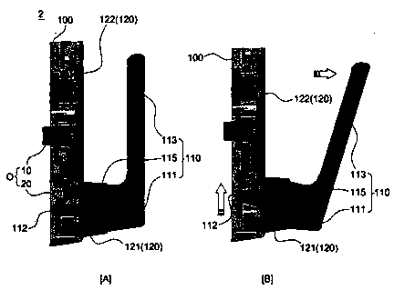
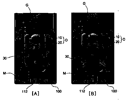
Door lock with push-pull handle
A handle and door lock technology, applied in handle connection, building locks, door/window accessories, etc., can solve problems such as inconvenience to open doors, danger, and inability to achieve locking, achieve easy manufacturing and combination, improve work stability, ensure The effect of manufacturing convenience
- Summary
- Abstract
- Description
- Claims
- Application Information
AI Technical Summary
Problems solved by technology
Method used
Image


Examples
Embodiment Construction
[0064] The present invention can be modified variously and has various forms, and the present invention will describe aspects (or embodiments) in detail in the text. However, this is not intended to limit the present invention to a specific disclosed form, and it should be understood that the present invention includes all changes, equivalents, and substitutions included within the spirit and technical scope of the present invention.
[0065] In the various drawings, the same reference numerals, especially the tens digit and one digit or the same reference numerals for ten digits, one digit and Roman letters, indicate the same or components with similar functions, unless otherwise specified Note that components denoted by reference numerals in the drawings may be regarded as components conforming to this standard.
[0066] In addition, in consideration of convenience of understanding, etc., in each drawing, the size and thickness of constituent elements are exaggerated, shown ...
PUM
 Abstract
Description
Claims
Application Information
 - R&D Engineer
- R&D Manager
- IP Professional
- Industry Leading Data Capabilities
- Powerful AI technology
- Patent DNA Extraction
Browse by: Latest US Patents, China's latest patents, Technical Efficacy Thesaurus, Application Domain, Technology Topic, Popular Technical Reports.
© 2024 PatSnap. All rights reserved.Legal|Privacy policy|Modern Slavery Act Transparency Statement|Sitemap|About US| Contact US: help@patsnap.com