
A Braking Sensation Simulation Device Based on Motor Force

A technology for simulating device and motor force, applied in the direction of braking transmission, brake, transportation and packaging, etc., it can solve problems such as inability to produce drivers, inability to optimize driver's braking feeling, different braking feedback, etc., to increase battery life Mileage, optimized braking feeling, low cost effect

Active Publication Date: 2020-02-14
JIANGSU UNIV OF TECH
View PDF5 Cites 0 Cited by
  • Summary
  • Abstract
  • Description
  • Claims
  • Application Information

AI Technical Summary

Problems solved by technology

[0005] The purpose of the present invention is to overcome the defects in the prior art that different braking feedbacks to the driver cannot be generated and the driver’s braking feeling cannot be optimized, and to provide a braking feeling simulation device based on motor force, which can be used in different braking conditions. Under dynamic conditions, different braking feedback to the driver can be generated, which can optimize the driver's braking feeling

Method used


Image

  • A Braking Sensation Simulation Device Based on Motor Force
  • A Braking Sensation Simulation Device Based on Motor Force
  • A Braking Sensation Simulation Device Based on Motor Force

Examples


Embodiment Construction

[0022] The present invention is described in further detail now in conjunction with accompanying drawing. These drawings are all simplified schematic diagrams, which only illustrate the basic structure of the present invention in a schematic manner, so they only show the configurations related to the present invention.

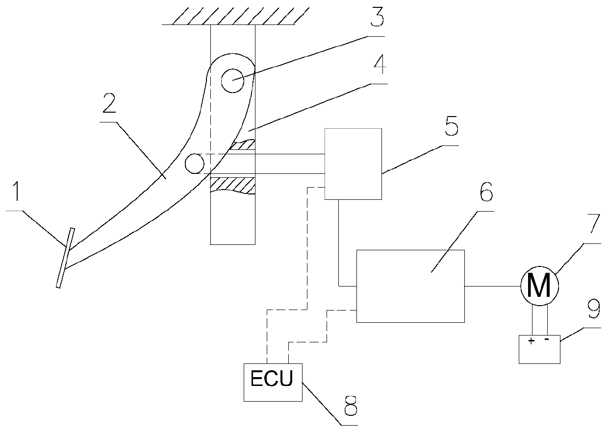
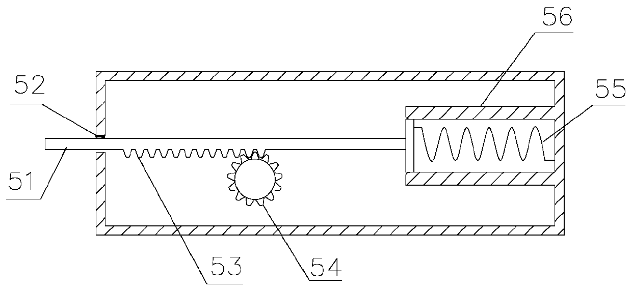
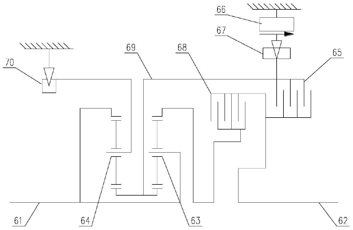
[0023] like Figure 1-Figure 2 Shown is a specific embodiment of a brake feeling simulation device based on motor force of the present invention, which includes a brake pedal assembly, a pedal feel simulator 5, a torque adjustment device 6, a motor 7 and an ECU 8; the pedal feel simulation The device 5 includes a push rod 51, a speed sensor 52 for measuring the moving speed of the push rod 51, a gear 54 and a buffer rebound mechanism, and the torque adjustment device 6 includes an input shaft 61 and an output shaft 62; one end of the push rod 51 is connected to the brake Pedal assembly, the other end is connected to the buffer rebound mechanism, the push rod ...


PUM


Abstract

The invention belongs to the technical field of automobile manufacturing, and in particular relates to a braking feeling simulation device based on motor force, comprising a brake pedal assembly, a pedal feeling simulator, a torque adjustment device, a motor and an ECU; the pedal feeling simulator includes a push rod 1. Speed ​​sensor, gear and buffer rebound mechanism for measuring the moving speed of the push rod. The torque adjustment device includes an input shaft and an output shaft; one end of the push rod is connected to the brake pedal assembly, and the other end is connected to the buffer rebound mechanism. The rod has a rack structure meshed with the gear, the gear is connected to the input shaft, and the output shaft is connected to the motor. The ECU receives the signal from the speed sensor and sends a control signal to the torque adjustment device. The beneficial effects of the invention are: different braking feedbacks to the driver are generated under different braking conditions, and the driver's braking feeling can be optimized; the structure is simple, the installation and operation are flexible, and the cost is low; the generator converts mechanical energy into electrical energy , Increase the cruising range of new energy vehicles.

Description

technical field [0001] The invention belongs to the technical field of automobile manufacturing, and in particular relates to a braking feeling simulation device based on motor force. Background technique [0002] Automotive wire control technology is a system that converts the driver's manipulation action into an electrical signal through a sensor, and directly transmits it to the actuator through a cable. Current control-by-wire technologies include shift-by-wire systems, brake-by-wire systems, suspension-by-wire systems, accelerator-by-wire systems, and steering-by-wire systems. In the future, with the maturity of control-by-wire technology and the reduction of cost and the impact of pursuing automatic driving, control-by-wire technology will be more and more used in ordinary vehicles. [0003] Brake-by-wire technology is a technology developed under the condition of wire-control technology, which can convert the driver's operation instructions into electrical signals, a...

Claims


Application Information

Patent Timeline
Patent Type & Authority Patents(China)
IPC IPC(8): B60T13/04B60T13/74B60T8/54B60T8/17
CPCB60T8/17B60T8/54B60T13/04B60T13/746
Inventor 沈应兴刘成晔周勋
Owner JIANGSU UNIV OF TECH
Learn More