Cement mixture stirrer

A technology for mixing materials and agitators, which is applied in cement mixing devices, mixing plants, mixing operation control, etc., can solve the problems that the weight of the eccentric block cannot be very large, the operation of the whole machine is unstable, and the mixing effect is affected, and the vibration force can be achieved. Large, low cost, improve the effect of stirring effect

Pending Publication Date: 2017-10-03
HEBEI ROAD & BRIDGE GROUP
View PDF0 Cites 0 Cited by
  • Summary
  • Abstract
  • Description
  • Claims
  • Application Information

AI Technical Summary

Problems solved by technology

The traditional eccentric cement-stabilized gravel vibrating mixing equipment has the following disadvantages: (1) The vibration force is small. Since the eccentric block of the eccentric cement-stabilized gravel vibrating mixer is designed and installed in the stirring shaft, it is limited by the structural size of the stirring shaft. The weight of the eccentric block cannot be very large, and the vibration force is small, which will affect the stirring effect
(2) The working noise is high. When the eccentric cement stabilized gravel vibrating mixer is working, the vibrating stirring shaft will impact the casing and the stone under the action of the exciting force. The working noise is very loud, which affects the lives of nearby residents and often causes complaint
(3) The life of the vibrating shaft is short. When the eccentric cement stabilized gravel vibrating mixer is working, the vibrating stirring shaft will impact the casing and the stone under the action of the exciting force, which will easily cause damage to the vibrating shaft and the life of the vibrating shaft is short.
(4) The work of the whole machine is unstable. Due to the short life of the vibration shaft, the vibration shaft must be replaced frequently, resulting in unstable work of the whole machine
(5) Difficult maintenance and high cost. When the eccentric cement stabilized gravel vibrating mixer fails, it is often necessary to replace the vibrating shaft and the vibrating block together. The maintenance cost is high, and the disassembly and assembly is time-consuming, laborious and expensive.

Method used


Image

  • Cement mixture stirrer
  • Cement mixture stirrer
  • Cement mixture stirrer

Examples


Embodiment Construction

[0027] The present invention will be further described in detail below in conjunction with the accompanying drawings and specific embodiments.

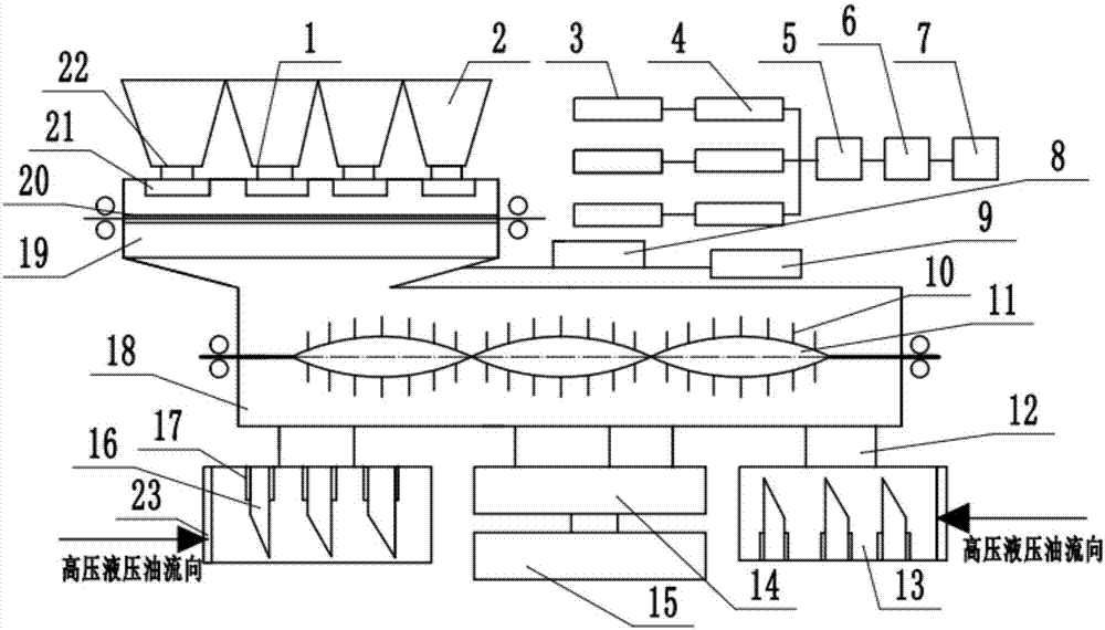
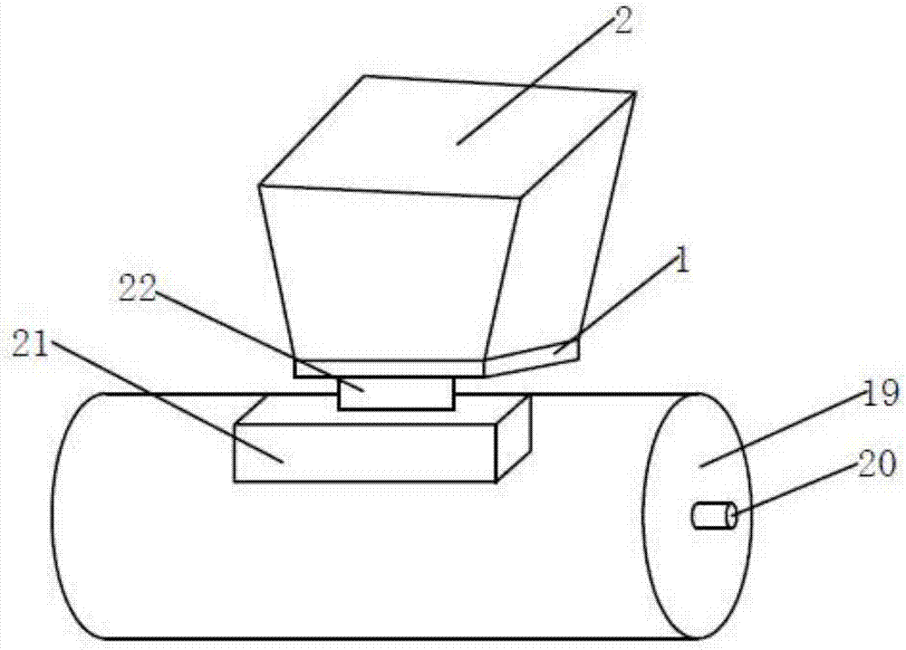
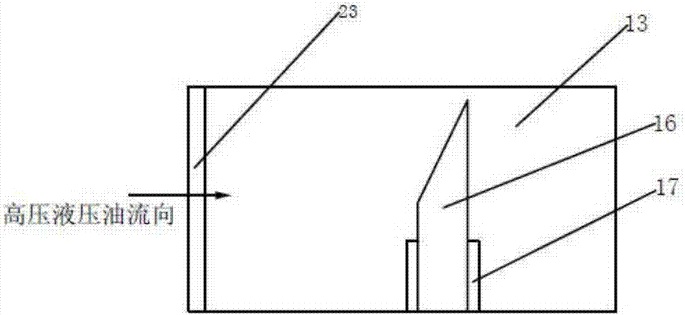
[0028] Depend on Figure 1-4 As can be seen from the shown embodiment, the present invention comprises a stone material supply device, a stirring device, a vibrating device, a vibrator coupling device 12 and a hydraulic power unit, and the stone material supply device comprises a plurality of stone material hoppers 2 set up side by side, and at the exit of each stone material hopper 2 The material opening 1 is provided with a material door switch 22, and the central connection line of the discharge opening 1 of each stone hopper 2 is located on the same horizontal line, and a rotating proportioner measured by volume is provided below each stone hopper 2: including a drum support 19 , the rotating shaft 20 of the roller bracket 19 is arranged in parallel directly below the central connection line, and each stone hopper 2 is provided wi...


PUM


Abstract

The invention discloses a cement mixture stirrer. The cement mixture stirrer comprises a stone supply device, a stirring device, a vibrating device, a vibrator connecting device and a hydraulic power device, wherein the stone supply device comprises a plurality of stone funnels which are arranged side by side; a material gate switch is arranged in a discharge hole of each stone funnel; a rotary proportioner which meters in volume is arranged below each stone funnel; the rotary proportioner comprises a roller bracket, wherein the rotary shaft of the roller bracket is arranged below center connecting lines in parallel; each stone funnel is equipped with storage boxes of the same quantity; the storage boxes of each stone funnel are arranged in the peripheral direction around the roller bracket below respective discharge hole; when the roller bracket rotates, the storage boxes of each stone funnel simultaneously reach the position below the discharge hole of the respective stone funnel in sequence; each storage box is in threaded connection with the roller bracket; and the rotary proportioner which meters in volume is arranged above a charge hole of the stirring device. The cement mixture stirrer has the characteristics of stable stone grading, sufficient stirring, a long service life of a vibrating system, stable work of the whole machine, convenient maintenance, and the like.

Description

technical field [0001] The invention relates to a cement mixture mixer. Background technique [0002] Cement-stabilized macadam base is a major pavement structure form of my country's highways. The cement-stabilized macadam mixture is currently constructed using traditional eccentric cement-stabilized macadam vibrating mixing equipment. The traditional eccentric cement-stabilized gravel vibrating mixing equipment has the following disadvantages: (1) The vibration force is small. Since the eccentric block of the eccentric cement-stabilized gravel vibrating mixer is designed and installed in the stirring shaft, it is limited by the structural size of the stirring shaft. The weight of the eccentric block cannot be very large, and the vibration force is small, which will affect the stirring effect. (2) The working noise is high. When the eccentric cement stabilized gravel vibrating mixer is working, the vibrating stirring shaft will impact the casing and the stone under the act...

Claims


Application Information

Patent Timeline
Patent Type & Authority Applications(China)
IPC IPC(8): B28C5/14B28C5/48B28C7/04B28C7/06
CPCB28C5/14B28C5/48B28C7/0481B28C7/067
Inventor 赵月平李伟杜欣峰张文利王飞
Owner HEBEI ROAD & BRIDGE GROUP
Why Eureka
Try Eureka