
Automatic drilling and detecting machine for lampholder manufacturing

A detection machine and automatic technology, applied in the direction of boring/drilling, drilling/drilling equipment, manufacturing tools, etc., can solve the problems of low efficiency of manual assisted conduction, damage to lamp holder, small size of wire hole 103, etc. Achieve the effect of ensuring preparation efficiency and finished product quality

Inactive Publication Date: 2017-10-03
苏州睿立汇自动化科技有限公司
View PDF12 Cites 2 Cited by
  • Summary
  • Abstract
  • Description
  • Claims
  • Application Information

AI Technical Summary

Problems solved by technology

[0005] 1) The auxiliary conduction of the wire hole 103 is performed manually. Since the wire hole 103 has a small specification, the efficiency of the manual auxiliary conduction is low, and the wire hole 103 is easy to be damaged;
[0006] 2) There are burrs on the ear 101, which are also removed manually, which is inefficient and easy to cause damage to the lamp holder 100

Method used


Image

  • Automatic drilling and detecting machine for lampholder manufacturing
  • Automatic drilling and detecting machine for lampholder manufacturing
  • Automatic drilling and detecting machine for lampholder manufacturing

Examples


Embodiment 1

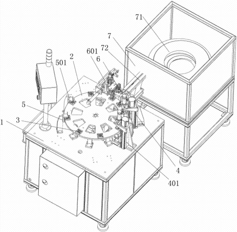
[0047] see figure 1 , 3 , 4, 5, 6, this embodiment shows an automatic drilling inspection machine for lamp holder preparation:

[0048] It includes an index plate 2 rotatably arranged on the frame 1, a number of carriers 3 uniformly arranged on the index plate 2, distributed around the index plate 2 and corresponding to and matched with the carriers 3 The used drilling assembly a 4, drilling assembly b401, detection assembly a 5, and detection assembly b 501;

[0049] In this embodiment, the number of carriers 3 is not limited, and the number of carriers 3 can be set according to production needs;

[0050] The indexing plate 2 is also correspondingly provided with a feeding assembly 7, and the frame 1 is provided with a feeding assembly 6 used in conjunction with the feeding assembly 7 and the carrier 3 provided on the indexing plate 2 respectively, and the frame 1 A blanking assembly 601 used in conjunction with the index plate 2 is also provided.

[0051] The feeding as...

Embodiment 2

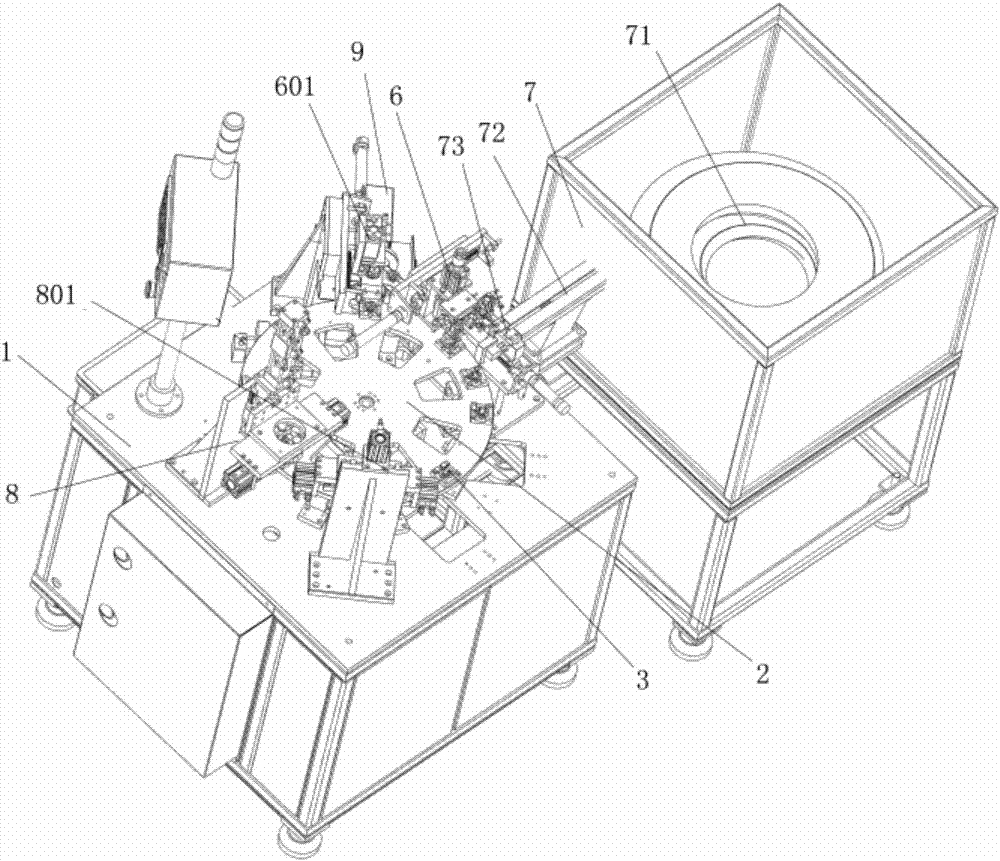
[0066] refer to figure 2 , 3 , 4, 7, 8, this embodiment shows an automatic deburring inspection machine for lamp holder preparation:

[0067] It includes an index plate 2 rotatably arranged on the frame 1, a number of carriers 3 uniformly arranged on the index plate 2, distributed around the index plate 2 and corresponding to and matched with the carriers 3 The deburring assembly a 8 and the deburring assembly b 801 used, the index plate 2 is also provided with the feed assembly 7 correspondingly, and the frame 1 is provided with the carrier 3 that is respectively arranged on the feed assembly 7 and the index plate 2 The feeding assembly 6 used in conjunction with the frame 1 is also provided with the unloading assembly 601 used in conjunction with the index plate 2 and the detection assembly c 9 used in conjunction with the unloading assembly 601 .

[0068] In this embodiment, the number of carriers 3 is not limited, and the number of carriers 3 can be set according to pro...


PUM


Abstract

The invention discloses an automatic drilling and detecting machine for lampholder manufacturing. The automatic drilling and detecting machine comprises an index plate rotationally arranged on a machine frame, a plurality of carriers uniformly arranged on the index plate, a drilling assembly a, a drilling assembly b, a detection assembly a and a detection assembly b, wherein the drilling assembly a, the drilling assembly b, the detection assembly a and the detection assembly b are distributed with the index plate as the center, correspond to the carriers and are cooperatively used with the carriers; the index plate is further provided with a feeding assembly in a corresponding mode; the machine frame is provided with a loading assembly which is cooperatively used with the feeding assembly and the carriers arranged on the index plate; and the machine frame is further provided with a discharging assembly which is used with the index plate in a matched mode. The automatic drilling and detecting machine can automatically conduct drilling and communicating treatment on wire holes in a lampholder, and the lampholder manufacturing efficiency and finished product quality are ensured.

Description

technical field [0001] The invention relates to the field of automation equipment, in particular to an automatic drilling inspection machine for lamp holder preparation. Background technique [0002] Such as Figure 9 As shown, it shows a lamp holder 100, which has a lamp holder main body 101 and an ear portion 102 arranged on the lamp holder main body; two corresponding wire holes 103 need to be provided in the middle of the lamp holder main body 101; [0003] The current manufacturing method of the lamp holder 100 is generally to directly form the lamp holder main body 101 and the wire hole 102 through injection molding, and then use manual auxiliary conduction for the wire hole 103, and at the same time, the ear part 102 is also directly fixed on the lamp during the injection molding process. On the seat main body 101; [0004] The current preparation method of the lamp holder 100 has the following defects: [0005] 1) The auxiliary conduction of the wire hole 103 is pe...

Claims


Application Information

Patent Timeline
Patent Type & Authority Applications(China)
IPC IPC(8): B23B39/16B23Q17/20
CPCB23B39/16B23Q17/20
Inventor 徐乐
Owner 苏州睿立汇自动化科技有限公司
Learn More