wireless power transfer system
A wireless power transmission, power technology, applied in circuits, inductors, electrical components, etc.
- Summary
- Abstract
- Description
- Claims
- Application Information
AI Technical Summary
Problems solved by technology
Method used
Image

Examples
no. 1 approach
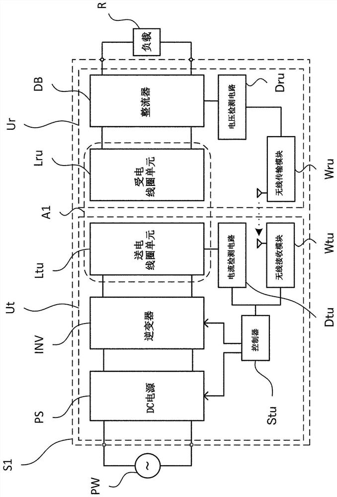
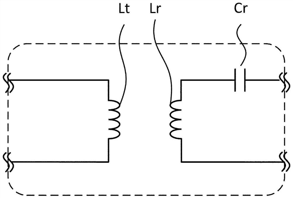
[0031] First, refer to figure 1 and figure 2 , the overall configuration of the wireless power transmission system S1 according to the first embodiment of the present invention will be described. figure 1 It is a block diagram showing the configuration of the wireless power transmission system according to the first embodiment of the present invention together with an AC power supply PW and a load R. figure 2 is enlarged figure 1 The shown partial enlarged view of area A1 in the wireless power transmission system according to the first embodiment of the present invention.
[0032] Such as figure 1 As shown, the wireless power transmission system S1 has a power transmitting device Ut and a power receiving device Ur.
[0033] The power transmission device Ut has a DC power supply PS, an inverter INV, a power transmission coil unit Ltu, a current detection circuit Dtu, a controller Stu, and a wireless reception module Wtu. The power receiving device Ur has a rectifier DB, ...
no. 2 approach
[0055] Next, a wireless power transmission system according to a second embodiment of the present invention will be described. In this embodiment, in the operation of the wireless power transmission system S1 according to the first embodiment, small power supply is performed using at least two or more different output voltages of the rectifier DB instead of a desired output voltage of the rectifier DB. is different from the first embodiment. In addition, the configuration of the wireless power transmission system according to the present embodiment is the same as that of the wireless power transmission system S1 according to the first embodiment. Hereinafter, description will focus on points different from the first embodiment.
[0056] The operation of the wireless power transmission system of this embodiment is divided into two steps. First, the first step is to obtain a small power supply of the peak value of the AC current flowing through the power transmission coil Lt c...
no. 3 approach
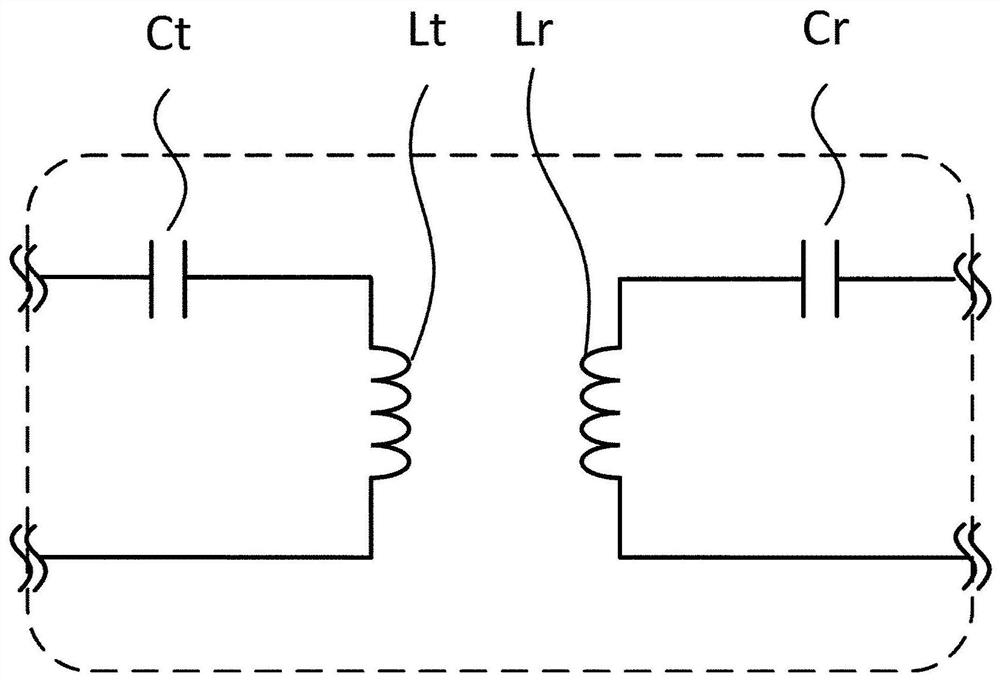
[0063] Next, refer to image 3 , the wireless power transmission system according to the third embodiment of the present invention will be described. image 3 is equivalent to zooming in figure 1In the shown partial enlarged view of the area A1 in the wireless power transmission system according to the first embodiment of the present invention, an enlarged partial enlargement of the area A1 in the wireless power transmission system according to the third embodiment of the present invention is shown. picture. The wireless power transmission system according to the third embodiment differs from the first embodiment in that the power transmission coil unit Ltu further includes a power transmission side resonant capacitor Ct in addition to the power transmission coil Lt. In addition, the configuration and operation of the wireless power transmission system according to the third embodiment other than those described above are the same as those of the wireless power transmission ...
PUM
 Abstract
Description
Claims
Application Information
 - Generate Ideas
- Intellectual Property
- Life Sciences
- Materials
- Tech Scout
- Unparalleled Data Quality
- Higher Quality Content
- 60% Fewer Hallucinations
Browse by: Latest US Patents, China's latest patents, Technical Efficacy Thesaurus, Application Domain, Technology Topic, Popular Technical Reports.
© 2025 PatSnap. All rights reserved.Legal|Privacy policy|Modern Slavery Act Transparency Statement|Sitemap|About US| Contact US: help@patsnap.com