
Method for constructing simulation model of converter cabinet body vibration

A converter cabinet and simulation model technology, applied in design optimization/simulation, instruments, special data processing applications, etc., can solve the problems of simulation model input deviation, low simulation accuracy, complexity, etc., to improve guidance, High degree of simulation and good accuracy

Active Publication Date: 2017-09-29
ZHUZHOU CSR TIMES ELECTRIC CO LTD
View PDF4 Cites 24 Cited by
  • Summary
  • Abstract
  • Description
  • Claims
  • Application Information

AI Technical Summary

Problems solved by technology

However, the vibration problem involves multi-disciplinary and multi-physical fields, which is quite complicated. The current simulation analysis has the following problems: 1) There is no complete analysis process
Most of the literature focuses on a certain aspect of the vibration problem, and seldom makes a reasonable combination of the converter finite element model correction and load identification
2) The simulation accuracy is not high
Because the finite element calculation requires some simplification of the system, for example, some nonlinear parameters become linear parameters, so that the finite element calculation model does not fully represent the real physical model, so that the finite element calculation results have some deviations from the real results
Modal analysis is the basis of various dynamic analysis types. Many calculation results are obtained based on modal superposition. Most of the existing simulation models do not consider the comparison and sensitivity analysis between the simulation mode and the test mode. As a result, the input of the simulation model is biased, and the errors are continuously accumulated in the subsequent links, which eventually leads to low simulation accuracy, which makes the usability of the simulation results worse, and does not give full play to the guidance value that the simulation model should have.

Method used


Image

  • Method for constructing simulation model of converter cabinet body vibration
  • Method for constructing simulation model of converter cabinet body vibration
  • Method for constructing simulation model of converter cabinet body vibration

Examples


Embodiment Construction

[0035] The present invention will be further described below in conjunction with the accompanying drawings and specific preferred embodiments, but the protection scope of the present invention is not limited thereby.

[0036] The vibration problem of the converter cabinet belongs to the vibration problem of the multi-degree-of-freedom system, and its dynamic equation is a coupled equation, which is difficult to solve directly. , can transform the coupled equations into linear equations, therefore, the modal superposition method is a very widely used calculation method in engineering applications, and it is also the basis of other dynamic analysis types. From the perspective of engineering calculation, it is not necessary to calculate all the modes. On the one hand, it is impossible to calculate all the modes for a system with a large number of degrees of freedom. On the other hand, engineering practice proves that under certain dynamic loads Not all modes can be excited. There...


PUM


Abstract

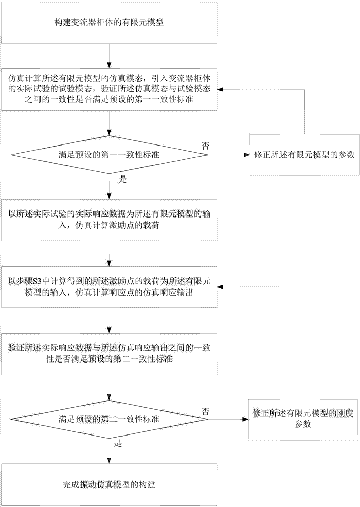
The invention discloses a method for constructing a simulation model of converter cabinet body vibration. The method includes the steps that 1, a finite element model of a converter cabinet body is constructed; 2, the simulation modality of the finite element model is calculated, the test modality of the converter cabinet body is introduced, whether the consistency of the simulation modality and the test modality meets a preset first consistency standard is verified, if yes, step 3 is carried out, and if not, parameters of the finite element model are amended, and the step 2 is repeated; 3, the actual response data of an actual test is used as the input of the finite element model, and the load of an exciting point is calculated; 4, the load of the exciting point is used as the input of the finite element model, and the simulation response output of a response point is calculated; 5, whether the consistency between the actual response data and the simulation response output meets a preset second consistency standard is verified, if yes, construction of the simulation model is completed, and if not, the rigidity parameter of the finite element model is amended, and the step 4 is carried out. The method has the advantages that the accuracy of simulation results obtained by the simulation model and high simulation precision are ensured.

Description

technical field [0001] The invention relates to the technical field of vibration simulation, in particular to a method for constructing a vibration simulation model of a converter cabinet used in rail traffic such as trains. Background technique [0002] Converters for rail transit vehicles can be divided into traction converters and auxiliary converters, which are important equipment for the normal operation of rail transit vehicles. From the perspective of functional structure, these converters can basically be divided into cabinets and electrical components (such as converter modules, control boxes, transformers, reactors, fans, contactors, busbars and wires, etc.). Electromagnetic components such as transformers and reactors will generate large electromagnetic vibrations due to the magnetostrictive effect during work; fans will generate large mechanical vibrations due to large power, high speed, and large wind pressure and flow; contact The device will generate a large ...

Claims


Application Information

Patent Timeline
IPC IPC(8): G06F17/50
CPCG06F30/23
Inventor 丁杰刘海涛李华王永胜曾亚平夏亮臧晓斌李振鹏
Owner ZHUZHOU CSR TIMES ELECTRIC CO LTD
Learn More