Buffering regulation mechanism for roller of suction plate

A buffer adjustment and roller technology, applied in the field of road sweepers, can solve the problems of labor and time, shortened service life, and wear of rollers.

Pending Publication Date: 2017-09-29
JINGSU YUEDA SPECIAL VEHICLE CO LTD
View PDF0 Cites 0 Cited by
  • Summary
  • Abstract
  • Description
  • Claims
  • Application Information

AI Technical Summary

Problems solved by technology

It can be seen from the above that when it is necessary to adjust the position of the roller relative to the main body of the suction cup, at least three bolts need to be adjusted, which is not only troublesome, but also labor-intensive and time-consuming
In addition, when the roller encounters an obstacle, the impact force of the obstacle often causes the wear of the roller and the deformation of the roller pin, shortening the service life
At the same time, when the roller encounters an uneven road surface, the roller will often hang in the air on the uneven road surface, causing the main body of the suction cup to lose balance, resulting in the phenomenon that the lower edge of the main body of the suction cup is ground.

Method used


Image

  • Buffering regulation mechanism for roller of suction plate
  • Buffering regulation mechanism for roller of suction plate
  • Buffering regulation mechanism for roller of suction plate

Examples


Embodiment Construction

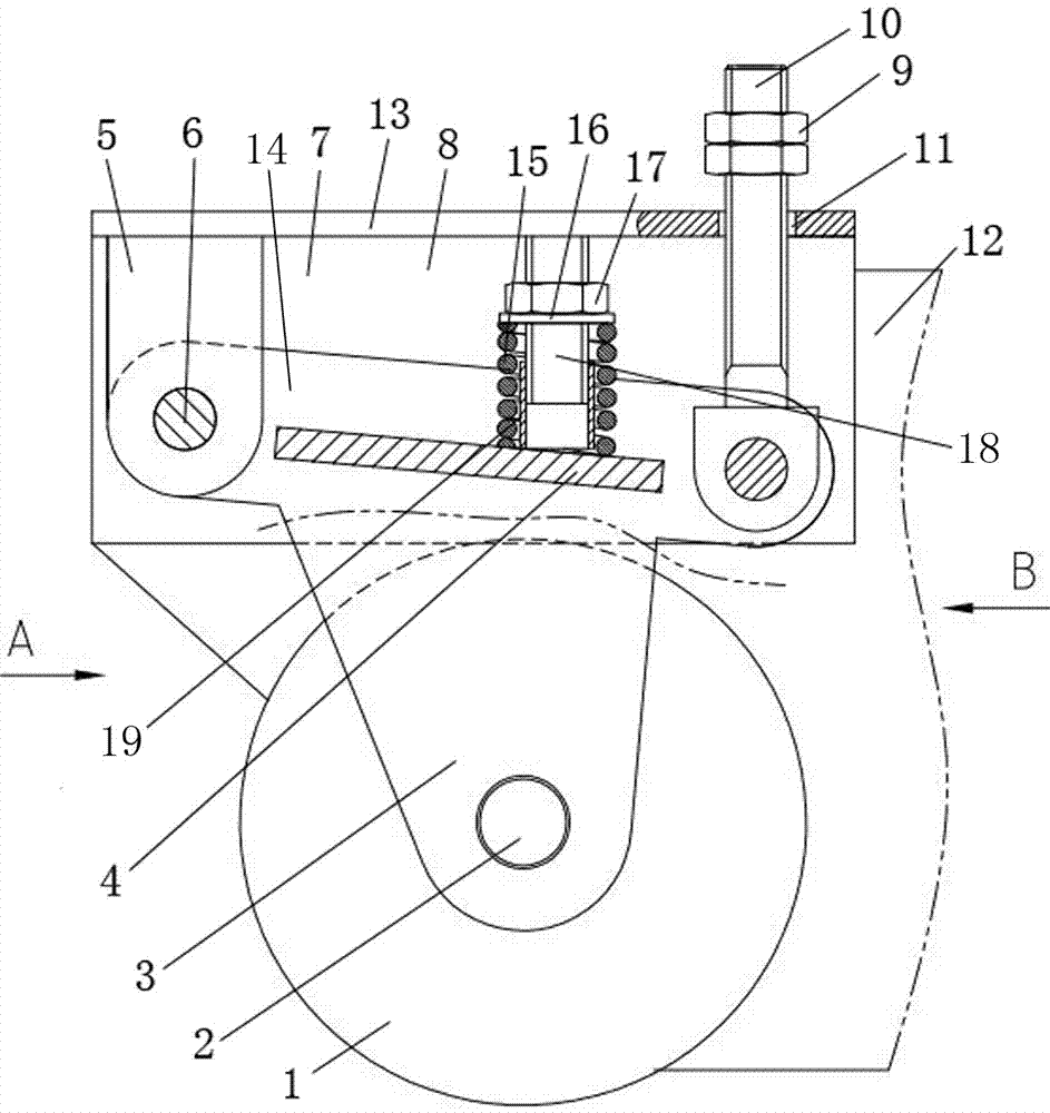
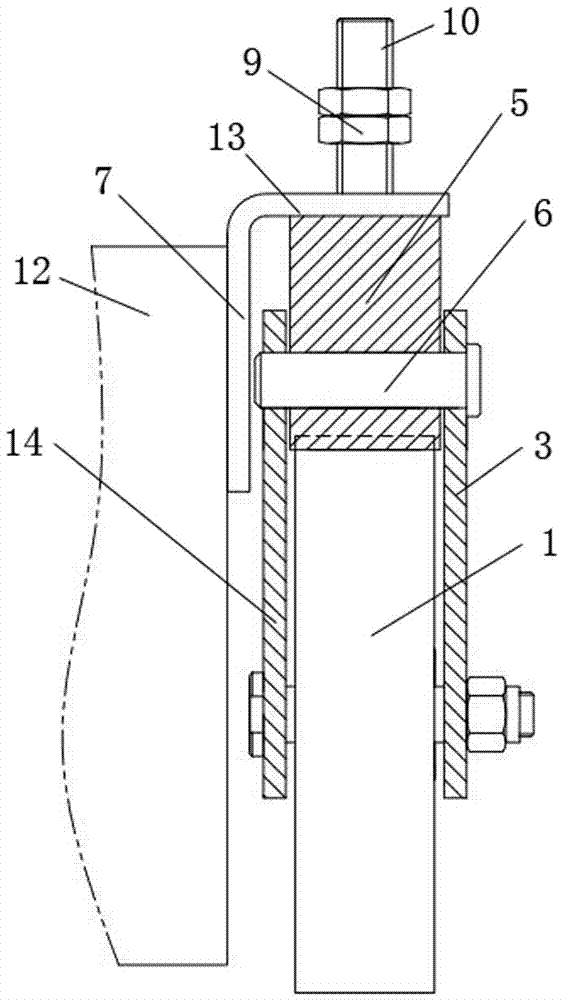
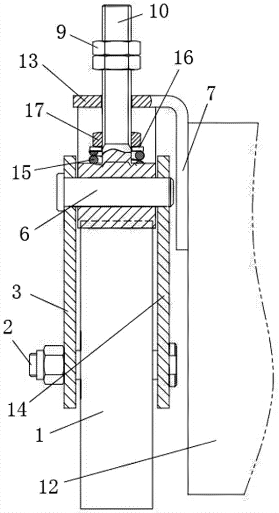
[0010] figure 1 , figure 2 and image 3 Among them, the present invention discloses a suction cup roller buffer adjustment mechanism, which includes a roller 1, a roller bracket, an adjusting bolt 10, a fixing seat 8, a connecting seat 5, a supporting bolt 18, a spring 15 and a guide sleeve 19. The fixing seat is an angle steel structure including a top surface 13 and a side surface 7 . The upper end of the connecting seat 5 is arranged below the front part of the top surface 13 of the fixing seat 8 . Described roller support comprises side plate one 3 and side plate two 14, and side plate one 3 and side plate two 14 have the same structure. Roller 1 is contained in the inner lower part between side plate one 3 and side plate two 14 by lower bearing pin 2. The bottom of connecting seat 5 is contained in the upper front part between side plate one 3 and side plate two 14 by bearing pin 6. The lower end of the adjusting bolt 10 is positioned at the upper rear portion betwe...


PUM


Abstract

The invention discloses a sucker roller buffer adjustment mechanism, which comprises a roller, a roller bracket, an adjusting bolt, and also includes a fixing seat, a connecting seat, a supporting bolt, a spring and a guide sleeve. The roller bracket includes a side plate one and a side plate two, connected The lower part of the seat is installed on the upper front part between the side plate 1 and the side plate 2 through the pin shaft, the lower end of the adjusting bolt is located at the upper rear part between the side plate 1 and the side plate 2 and forms a hinge, and the upper end of the adjusting bolt Located in the waist-shaped hole at the rear of the top surface of the fixing seat, the upper end of the adjusting bolt is equipped with a lock nut, and the lock nut is located above the top surface of the fixing seat, in the upper middle part between the side plate 1 and the side plate 2 There is a connecting plate, the upper end of the support bolt is set under the middle part of the top surface of the fixed seat, the guide sleeve is set on the support bolt, the spring is set on the guide sleeve and the support bolt, and the support bolt is equipped with a spring limit ring and an adjustment nut. The lower end of the spring is located on the upper surface of the connecting plate.

Description

technical field [0001] The invention relates to a road sweeper, in particular to a suction cup roller buffer adjustment mechanism. Background technique [0002] An existing road sweeper includes a suction cup assembly. The suction cup assembly includes a suction cup main body, a roller, a roller bracket, a limit bolt and a limit bolt seat. The roller is set on the roller bracket, and there are two waist-shaped grooves on the roller bracket, and two bolts are installed in the two waist-shaped grooves of the roller bracket and the screw holes on the side of the main body of the suction cup, so that the roller bracket is fixed on the on the side of the suction cup body. The limit bolt seat is arranged on the side of the suction cup main body, the limit bolt is worn on the adjusting bolt seat, and the lower end of the limit bolt bears on the roller bracket. When the roller is worn out and the position of the roller relative to the main body of the suction cup needs to be adju...

Claims


Application Information

Patent Timeline
Patent Type & Authority Applications(China)
IPC IPC(8): E01H1/08
CPCE01H1/08
Inventor 季明烨沈卫琴李婷吴新芳
Owner JINGSU YUEDA SPECIAL VEHICLE CO LTD
Why Eureka
Try Eureka