
Tiltable roller machine and automobile cavity wax injection technology achieving implementation through tiltable roller machine

A rolling bed and bed body technology, which is applied in the field of wax injection in automobile cavities, can solve problems such as difficulty in filling wax liquid, and achieve high wax injection and cooling efficiency, stable process, and improved efficiency.

Active Publication Date: 2017-09-29
盐城优德利自动化工程有限公司
View PDF3 Cites 2 Cited by
  • Summary
  • Abstract
  • Description
  • Claims
  • Application Information

AI Technical Summary

Problems solved by technology

During the process of wax injection, there is no relative movement between the car shell and the wax injection machine, and it is difficult to completely fill the corners of the inner cavity of the car shell with wax liquid
There is currently no known device that effectively solves this problem

Method used


Image

  • Tiltable roller machine and automobile cavity wax injection technology achieving implementation through tiltable roller machine
  • Tiltable roller machine and automobile cavity wax injection technology achieving implementation through tiltable roller machine
  • Tiltable roller machine and automobile cavity wax injection technology achieving implementation through tiltable roller machine

Examples


Embodiment 1

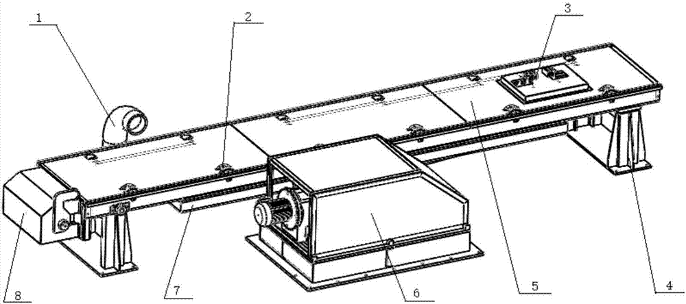
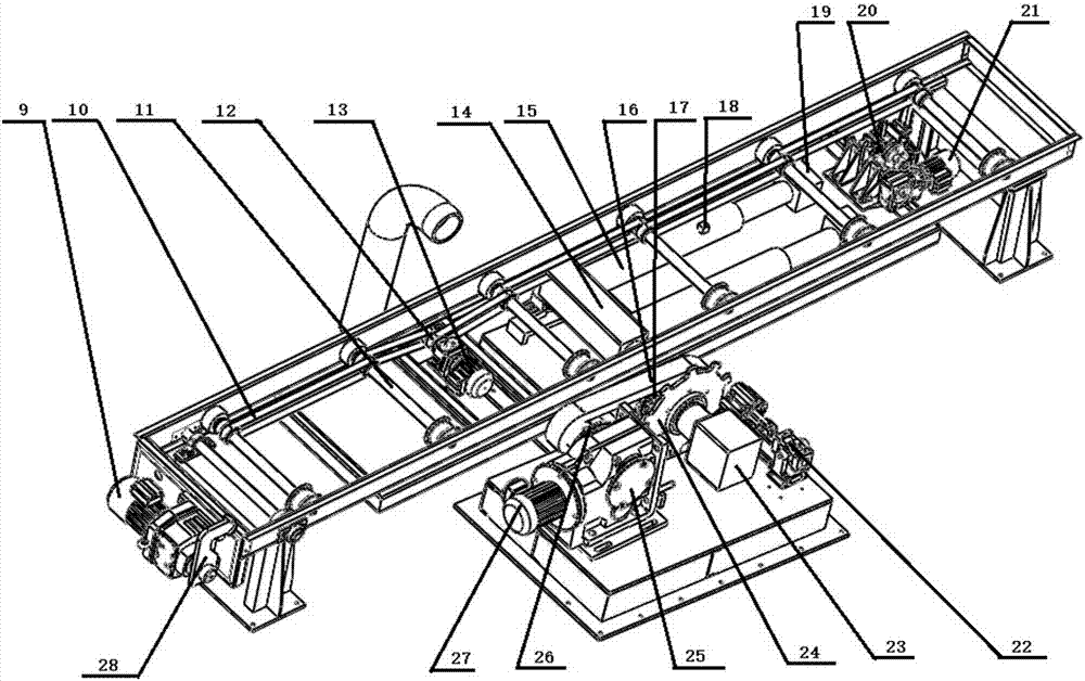
[0041] Such as figure 1 and 2 The tilting trundle shown includes:

[0042] The bed body comprises a bed body drive motor 13, a drive pulley 12, a belt 10, a roller shaft 11 and a roller 2. After the bed drive motor 13 is started, the drive pulley 12 is driven to rotate, thereby driving the belt 10 to move. The lower roller shaft 11 rotates, and the rollers 2 are installed at both ends of the roller shaft 11, and rotate with it;

[0043] Tilt power unit 6 comprises tilt drive motor 27, tilt drive motor reducer 25, first pulley 26, synchronous belt 16, second pulley 17, connector 14, telescopic rod 15 and solenoid coil 19, tilt drive motor After 27 starts, drive the tilting drive motor reducer 25, the output shaft of the tilting drive motor reducer 25 is connected with the first pulley 26, the first pulley 26 rotates to drive the synchronous belt 16 to rotate, and then drives the second pulley 17 to rotate, The connecting piece 14 is rigidly connected with the output shaft of t...

Embodiment 2

[0052] Utilize the process in the wax injection of automobile cavity shown in embodiment 1 that can be inclined rolling bed to implement, comprise the following steps:

[0053] Step 1: Fix the treated car shell on the carrying tray, and the carrying tray is transported to the bed body of the tiltable roller bed through the roller conveyor, and the electric control device controls the tray to stop;

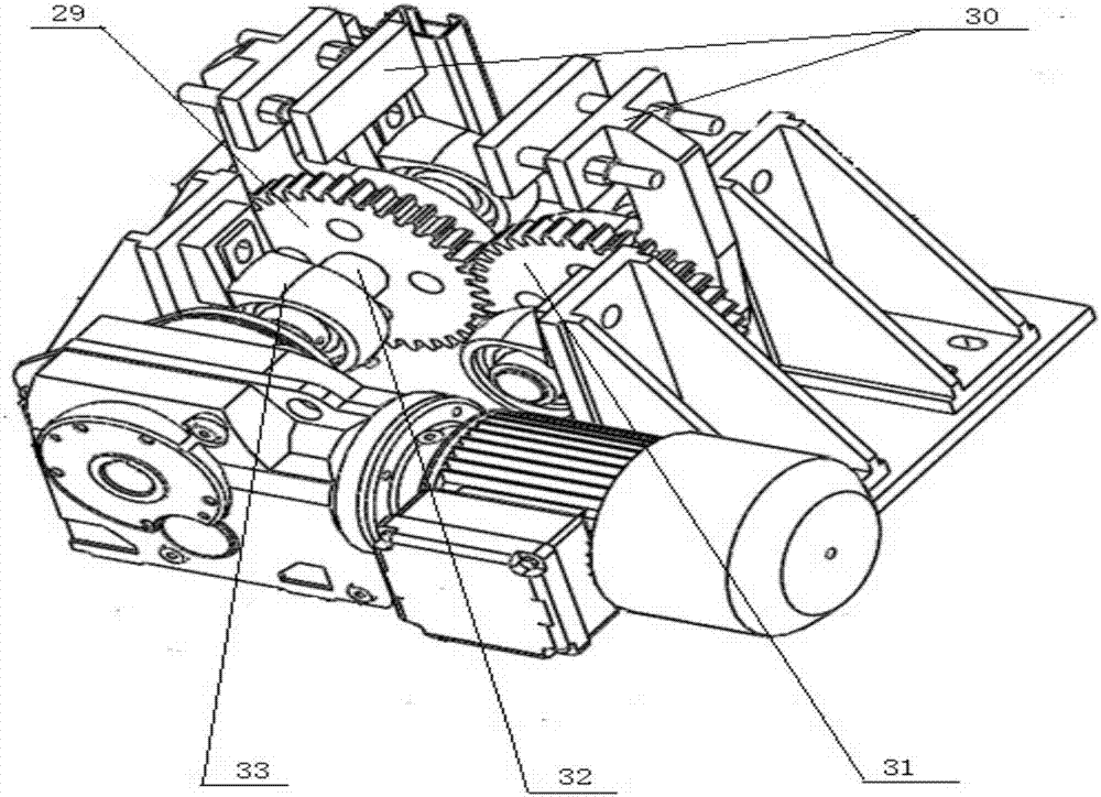
[0054] Step 2: Start the motor of the front-end clamping device, drive the front-end clamping arm to lift up, clamp the front end of the carrying tray, start the motor of the rear-end clamping device, drive the rear-end clamping arm to lift, and lift the rear beam of the carrying tray Clamp;

[0055] Step 3: Start the tilting drive motor, the tilting power unit is partially operated, and the telescopic rod is driven to lift up. At the same time, the solenoid coil is energized to make it magnetically adsorbed to the bed body, so that the bed body is lifted around the shaft axis, and...


PUM


Abstract

The invention discloses a tiltable roller machine which comprises a machine body, a tilt power device, a front end clamping assembly, a rear end clamping assembly, an underframe, a machine body upper cover plate, a front end clamping device cover plate and a tilt power device cover plate. The invention further discloses a novel automobile cavity wax injection technology achieving implementation with the help of the tiltable roller machine. The process of the technology comprises the steps of transporting, fixing, wax pre-injection after machine body tilting, cold air cooling and wax re-injection. The tiltable roller machine tilts through the tilt power device and components of the roller machine, and when the tiltable roller machine is applied to automobile cavity wax injection, the wax injection efficiency is higher; and the tilt angle of the roller machine can be adjusted to achieve uniform wax injection of corners of car shells.

Description

technical field [0001] The invention belongs to the automobile manufacturing technology, and in particular relates to a tiltable roller bed and a wax injection process for the automobile cavity implemented by using the same. Background technique [0002] With the improvement of people's living standards and the rapid development of science and technology, cars are becoming more and more popular, and many families buy cars as a means of transportation. The car body is made of metal materials. From the material point of view, as long as it is steel, it cannot avoid rusting, and galvanized steel sheets cannot completely prevent rusting. Therefore, in the manufacturing process of the car body, the exterior of the car body is generally treated with "cathode electrophoretic coating" for anti-rust treatment, but this does not prevent the occurrence of inner cavity corrosion. So there is another anti-corrosion technology-inner cavity wax injection. There are many cavities in the c...

Claims


Application Information

Patent Timeline
Patent Type & Authority Applications(China)
IPC IPC(8): B05C13/02B05D1/26
CPCB05C13/02B05D1/26
Inventor 冯伟张守伟安晶侯鹏亮卢倩董晓慧田晓峰
Owner 盐城优德利自动化工程有限公司
Learn More