Airborne bus performance navigation method
A navigation method and performance technology, applied in navigation, surveying and mapping and navigation, road network navigator, etc., can solve the problems of poor time synchronization and real-time performance
Active Publication Date: 2014-04-30
NORTHWESTERN POLYTECHNICAL UNIV
View PDF0 Cites 0 Cited by
- Summary
- Abstract
- Description
- Claims
- Application Information
AI Technical Summary
Problems solved by technology
[0004] In order to overcome the disadvantages of existing performance navigation methods in terms of time synchronization and navigation error fusion estimation, the real-time performance is poor
Method used
View moreImage
Smart ImageViewing Examples

Examples
Embodiment Construction
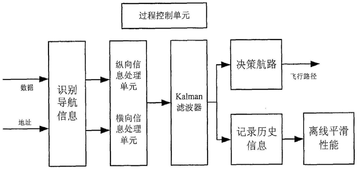
[0035] The software core of the system lies in the realization of the longitudinal information processor and the horizontal information processor. In obtaining the unified machine
[0038]
[0040]
[0043]
[0045]
[0049]
[0050]
[0051] ψ
Login to View More PUM
 Abstract
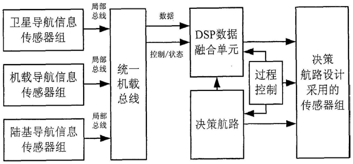
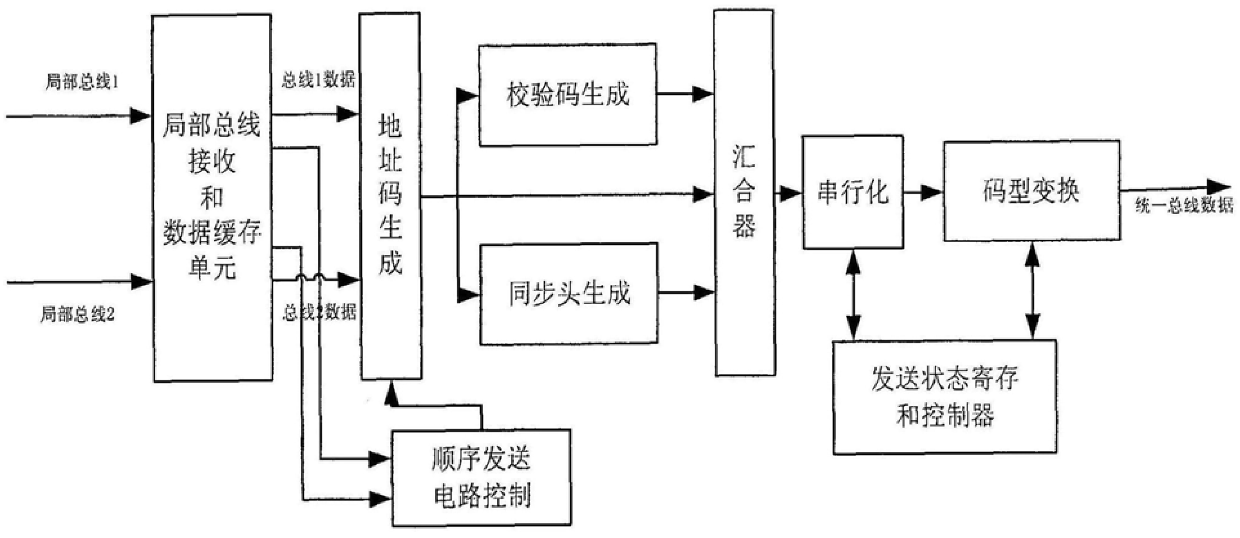
The invention relates to an airborne bus performance navigation method, which is used to solve the technical problem of poor real-time performance in time synchronization and navigation error fusion estimation of the existing performance navigation method. Its technical solution is to transform the navigation information obtained by different interfaces and buses into a unified bus and transmit it to the performance navigation processing center; the performance navigation processing center automatically classifies redundant navigation signals to the Vertical and horizontal performance navigation analysis module; according to the navigation information provided, the vertical and horizontal performance navigation module performs vertical and horizontal navigation error calculation respectively according to the model proposed by the present invention and the fusion estimation method of equivalent measurement; according to the navigation error, according to the performance navigation requirements , real-time navigation is realized in terms of time synchronization and navigation error fusion estimation.
Description
Airborne bus performance navigation method Technical field [0001] The present invention relates to a performance navigation method, in particular to an airborne bus performance navigation method. Background technique [0002] Performance navigation (PBN) has many advantages over sensor-based navigation, for example: it reduces the need to maintain specific The need for sensor routing and cost, avoiding the manipulation of specific sensors requiring navigation system improvements, clarifies practical Time-based navigation (RNAV) application methods, etc.; airborne performance monitoring is to determine whether the navigation system is in accordance with the navigation performance (RNP) standard An important factor for quasi-execution, it involves both longitudinal and lateral navigation performance, which is closely related to the airborne bus; the airborne unified machine The proposed bus provides a basis for realizing information fusion estimation based on multi-sensor ...
Claims
Login to View More Application Information
Patent Timeline
 IPC IPC(8): G01C21/00G01C21/28
Inventor 史忠科辛琪
Owner NORTHWESTERN POLYTECHNICAL UNIV
Features
- R&D
- Intellectual Property
- Life Sciences
- Materials
- Tech Scout
- Unparalleled Data Quality
- Higher Quality Content
- 60% Fewer Hallucinations
Learn More Browse by: Latest US Patents, China's latest patents, Technical Efficacy Thesaurus, Application Domain, Technology Topic, Popular Technical Reports.
© 2025 PatSnap. All rights reserved.Legal|Privacy policy|Modern Slavery Act Transparency Statement|Sitemap|About US| Contact US: help@patsnap.com