
Camera with multifunctional rack

A camera and multi-functional technology, applied in the field of cameras, can solve the problems of small support frame and cannot be provided by cameras, and achieve the effect of increasing protection performance and prolonging service life

Pending Publication Date: 2017-09-26
重庆万建电子工程有限责任公司
View PDF15 Cites 0 Cited by
  • Summary
  • Abstract
  • Description
  • Claims
  • Application Information

AI Technical Summary

Problems solved by technology

[0005] The invention provides a video camera with a multi-functional frame, which not only solves the problem that the existing selfie stick cannot be matched with the camera to realize the self-timer function, but also solves the problem that the camera cannot be provided with a small support frame in the prior art

Method used


Image

  • Camera with multifunctional rack
  • Camera with multifunctional rack
  • Camera with multifunctional rack

Examples


Embodiment Construction

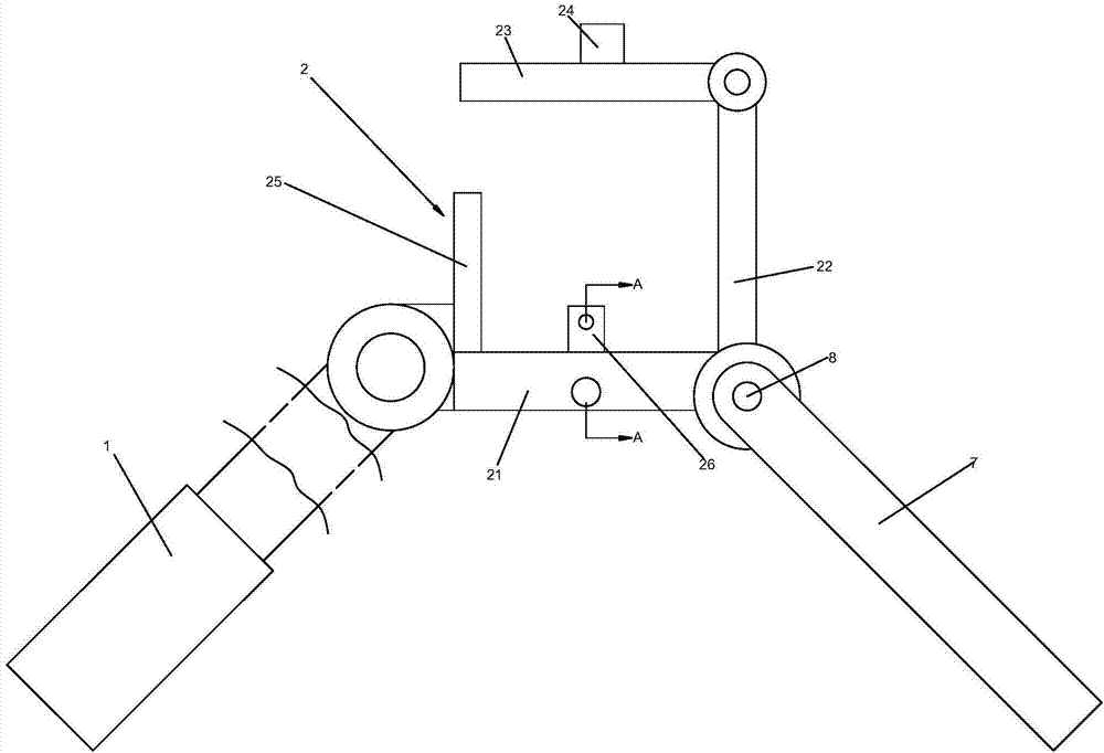
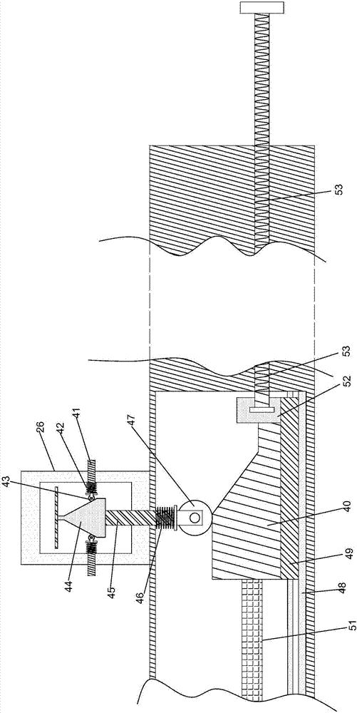
[0020] Such as figure 1Shown, a kind of video camera with multi-function stand comprises: camera body (not shown in the figure), and it comprises shell, and the bottom surface of shell is provided with at least two installation holes; And selfie stand, it comprises: selfie stick 1; Seat 2, it comprises base plate 21, rear baffle plate 22, top plate 23, button touch mechanism 24, two front baffle plates 25 and at least two insertion shafts 26, base plate 21 and selfie stick 1 end are fixed, two front baffle plates 25 all stand on On the edge of the bottom plate 21 close to the selfie stick 1, the gap between the two front baffles 25 is used for the camera of the camera body to pass through, and the back baffle 22 stands on the edge of the bottom plate 21 away from the selfie stick 1. The top is rotatably connected with a top plate 23, and a first rotation limiting mechanism is provided at the joint between the top plate 23 and the tailgate 22. When no external force acts on the...


PUM


Abstract

The invention provides a camera with a multifunctional rack. The camera with the multifunctional rack comprises a camera body comprising an outer shell, a selfie rack comprising a selfie stick, a mounting base and two support rods, the mounting base comprises a bottom plate, a rear baffle plate, a top plate, a key touch mechanism, two front baffle plates and at least two insertion shafts, the bottom plate is fixed with one end of the selfie stick, the two front baffle plates both stand on the edge, near to the selfie stick, of the bottom plate, the selfie stick is rotatably connected with the front edge of the bottom plate, a second rotation limiting mechanism is arranged on the joint between the selfie stick and the bottom plate, a mounting column vertical to each support rod is arranged at one end of the support rod, and a connecting mechanism located on the mounting column is arranged on each support rod. The camera with the multifunctional rack solves the problem that the existing selfie stick cannot be matched with the camera to realize the selfie function, and also solves the problem that a small support frame cannot be provided for the camera in the prior art.

Description

technical field [0001] The invention relates to a video camera, in particular to a video camera with a multi-function rack. Background technique [0002] A Chinese patent discloses a camera with application number 201620498286.5, which includes: a base, a mounting part is arranged on the base; a main body, the main body is mounted on the mounting part; an elastic locking part, the elastic locking part is mounted on the base, and Frictional contact with the main body self-locks the main body to the base. Although the camera avoids the deviation of the final locking angle caused by the process of tightening the bracket, the disadvantages of the camera are: [0003] 1) With the development of the times, people are more and more fond of traveling. Taking selfies during travel is the favorite thing for most tourists. Therefore, mobile phone selfie sticks have appeared to facilitate selfies with mobile phones. However, for the quality of shooting, mobile phones The shooting qual...

Claims


Application Information

Patent Timeline
IPC IPC(8): G03B17/56H04N5/225
CPCG03B17/561H04N23/50
Inventor 岳军刘春莲汪洋徐守中
Owner 重庆万建电子工程有限责任公司
Learn More