Box-shaped laminated heat exchanger provided with novel backing plate structure

A technology of heat exchangers and backing plates, which is applied in the field of box-shaped laminated heat exchangers, and can solve problems such as the sealing quality of backing plates, product scrapping, and heat exchange medium stringing chambers, etc.

Pending Publication Date: 2017-09-26
缪志先
View PDF10 Cites 0 Cited by
  • Summary
  • Abstract
  • Description
  • Claims
  • Application Information

AI Technical Summary

Problems solved by technology

[0004] The disadvantages of the above two published patents are that the periphery of the backing plate shown in this patent (028286839) and (ZL2013205973605) is a right-angled edge structure, and its peripheral right-angled edge structure is especially shown in the utility model patent (ZL2013205973605 )of Figure 5 , Image 6 , Figure 15, Figure 11 , Figure 13 and in Figure 15 etc.
However, there is an R connection transition between the inclined surface around each heat exchange plate and its bottom plane. When the backing plate is assembled in the heat exchange plate, the backing plate with right-angled edges may be biased to a single position in the heat exchange plate. As a result, the right-angled edges around the backing plate may ride on the R connection transition between the inclined surface around the heat exchange plate and the bottom plane, which will cause the plane of the backing plate and the bottom plane of the heat exchange plate to be inconsistent. A good fit will cause probl

Method used


Image

  • Box-shaped laminated heat exchanger provided with novel backing plate structure
  • Box-shaped laminated heat exchanger provided with novel backing plate structure
  • Box-shaped laminated heat exchanger provided with novel backing plate structure

Examples


Embodiment Construction

[0034] Further description will be made below in conjunction with embodiments and illustrations.

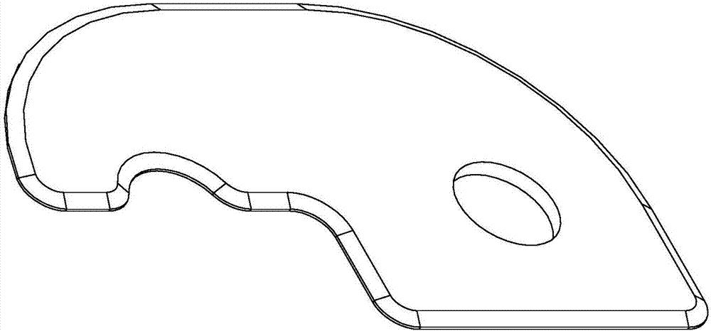
[0035] figure 1 The protruding structure of the backing plate with a protruding structure around it is continuous, and it can also be considered that the protruding structure around it is intermittent, and the meaning of the so-called protruding structure is intermittent should be the relevant engineering Those skilled in the art can understand and be familiar with, so do not draw and represent here again. In addition, it can be found that in figure 1 Indicates no assembly mark indents on backing plane.

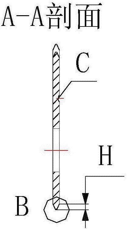
[0036] figure 2 with image 3 The C above means that there is an assembly mark indentation on a single surface of the backing plate, the indentation is shallow and obvious, and the depth, shape and position of the indentation should not hinder the sealing of the backing plate. In fact, it can also be understood as figure 1 The backing plate indicated is exactly figur...


PUM


Abstract

The invention discloses a box-shaped laminated heat exchanger provided with a novel backing plate structure. The box-shaped laminated heat exchanger consists of heat exchange plates which are provided with oblique surface edges, are box-shaped and can be mutually laminated in sequence. The oblique surfaces of the edges of the heat exchange plates are mutually connected in a sealing manner; in interlayers formed by the heat exchange plates in the box-shaped laminated heat exchanger, corner pores for a heat transfer medium to circulate and heat exchange devices for dividing wall heat exchange are formed and arranged; the heat exchange devices are located in the middles of the heat exchange plates correspondingly; the corner pores are distributed at the two ends of the heat exchange plates correspondingly; at the two ends of each heat exchange plate, in space formed by the corresponding corner pores and the peripheral expansion plane, backing plates in sealing connection with the upper and lower heat exchange plates are arranged; and one backing plate is arranged at each of the two ends of each heat exchange plate, and the two backing plates have the same thickness, and have the same thickness as that of the heat exchange device in the middle of the corresponding heat exchange plate. The box-shaped laminated heat exchanger is characterized in that in the box-shaped laminated heat exchanger, the backing plates assembled in the heat exchange plates and the peripheries of the backing plates are provided with bulged structures.

Description

technical field [0001] The invention relates to a heat exchanger, in particular to a box-shaped stacked heat exchanger with a novel pad structure. Background technique [0002] The box-shaped stacked heat exchanger is composed of a plurality of box-shaped heat exchange plates with beveled edges that can be stacked together in sequence. In the interlayer formed by the heat exchange plates in the device, there are corner holes for the circulation of the heat exchange medium and heat exchange devices for the heat exchange of the partition walls. The heat exchange devices are located in the middle of each heat exchange plate, and the corner holes are distributed in each At both ends of the heat exchange plate, in the space formed by the corner holes at both ends of the heat exchange plate and the peripheral extension surface, there is a backing plate that is sealed and connected with the upper and lower heat exchange plates. There is a backing plate at both ends, and the thickn...

Claims


Application Information

Patent Timeline
IPC IPC(8): F28D9/00F28F3/08F28F3/10
CPCF28D9/0043F28F3/08F28F3/10
Inventor 缪志先
Owner 缪志先
Why Eureka
Try Eureka