A suspension structure of a powertrain

A powertrain and suspension technology, which is applied to power plants, jet propulsion devices, internal combustion propulsion devices, etc., can solve the problems of easy disengagement of connecting bolts and elastic elements, easy to rotate with the nut, and to rotate with the nut, etc. Achieve the effect of increasing size, avoiding self-rotation, and eliminating additional torque

Active Publication Date: 2019-03-08
ZHEJIANG LEAPMOTOR TECH CO LTD
View PDF6 Cites 0 Cited by
  • Summary
  • Abstract
  • Description
  • Claims
  • Application Information

AI Technical Summary

Problems solved by technology

[0003] The purpose of the present invention is to solve the problem that the connecting bolts in the existing powertrain suspension structure are easy to rotate with the nut, so that the suspension spring generates an additional torque, and to provide a powertrain suspension structure, It can reliably locate the connecting bolt and prevent the connecting bolt from rotating with the nut, thereby effectively eliminating the additional torque of the suspension spring
[0004] Another object of the present invention is to solve the problem that the connecting bolts and elastic elements are easy to disengage in the power assembly suspension structure using rubber elastic elements, thereby reducing the connection reliability, and to provide a power assembly suspension The installation structure can effectively improve the connection strength and connection reliability between the connection bolt and the elastic element, which is beneficial to prolong the service life

Method used


Image

  • A suspension structure of a powertrain
  • A suspension structure of a powertrain
  • A suspension structure of a powertrain

Examples


Embodiment Construction

[0025] The present invention will be further described below in conjunction with the accompanying drawings and specific embodiments.

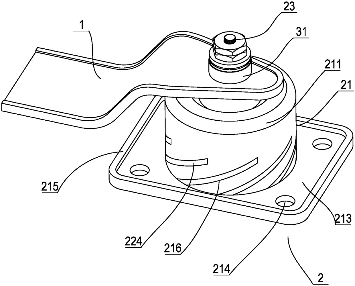
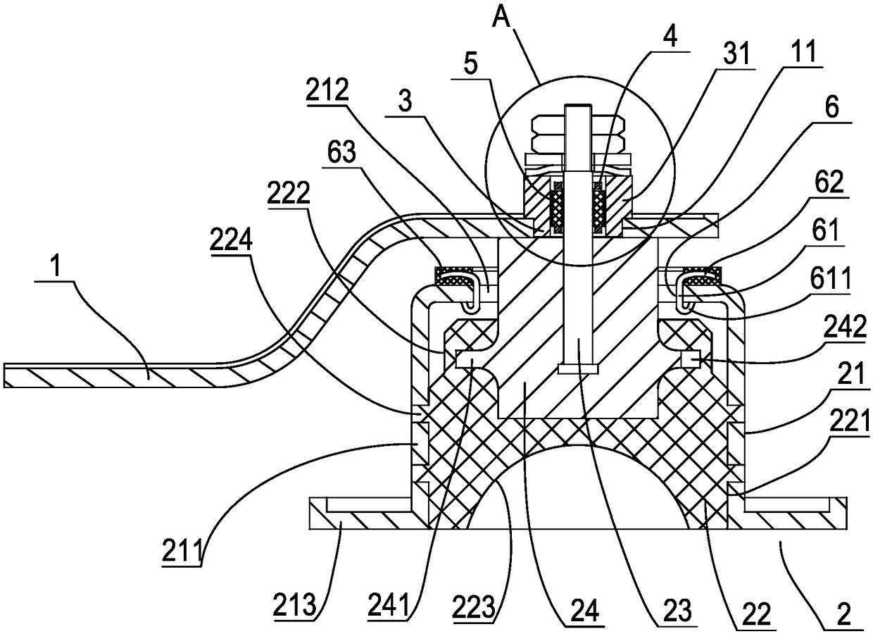
[0026] Such as figure 1 , figure 2 As shown, a suspension structure of a power assembly includes a suspension bracket 1 connected to the power assembly at one end, a suspension spring 2 arranged on the vehicle frame, the suspension spring includes a fixed casing 21, and is arranged on the fixed casing. Inside is an elastic element 22 made of rubber, and a connecting bolt 23 connected with the elastic element. The fixed shell includes a cylindrical protective shell 211, the lower end of which has an opening, and the elastic element is arranged in the protective shell. A connecting bolt through hole 212 is provided on the bottom wall of the upper part of the protective shell, and the upper end of the connecting bolt passes through the connecting bolt through hole upwards, and a rectangular mounting bottom plate 213 extending radially along the...


PUM


Abstract

The invention discloses a suspension structure of a power assembly. The suspension structure comprises a suspension support and a suspension spring. The suspension spring comprises a fixing shell, an elastic component and a connecting bolt, the elastic component is arranged in the fixing shell, the connecting bolt is connected with the elastic component and upwardly extends out of the fixing shell, a connecting through hole which is a regularly hexagonal hole is formed in the suspension support, a positioning sleeve in the shape of a regularly hexagonal prism is fittingly arranged in the connecting through hole, a positioning convex ring is arranged at the upper end of the positioning sleeve, an inner hole of the positioning sleeve is a regularly hexagonal hole, the connecting bolt comprises a positioning section and a threaded connecting section, the positioning section is positioned in the inner hole of the positioning sleeve, the threaded connecting section is coaxially connected onto the positioning section, a torque transmission structure is arranged between the positioning section and the inner hole of the positioning sleeve, a connecting block made of aluminum alloy is embedded in the elastic component, and the lower end of the connecting bolt is embedded in the connecting block. The suspension structure has the advantages that the connecting bolt can be reliably positioned and can be prevented from rotating along with nuts, and the strength of connection between the connecting bolt and the elastic component can be effectively improved.

Description

technical field [0001] The invention relates to an automobile power assembly structure, in particular to a power assembly suspension structure. Background technique [0002] The powertrain of the car is usually connected to the frame through the corresponding suspension structure during final assembly, so as to avoid transmitting the vibration of the powertrain to the frame during operation, and also to prevent the frame from being damaged when the vehicle is running. The vibration is reversely transmitted to the powertrain, causing the superposition of vibration. Usually, three left, right and rear suspension brackets are arranged on the powertrain, which are respectively connected to the suspension springs of the left longitudinal beam, the right longitudinal beam and the sub-frame, and the suspension springs include The vehicle frame is fixedly connected to the suspension spring casing, the elastic element arranged in the suspension spring casing, and the connecting bolt...

Claims


Application Information

Patent Timeline
Patent Type & Authority Patents(China)
IPC IPC(8): B60K5/12
CPCB60K5/1208
Inventor 吴海丰
Owner ZHEJIANG LEAPMOTOR TECH CO LTD
Why Eureka
Try Eureka