
Lower limb joint training device

A technology for training devices and joints, applied in passive exercise equipment, physical therapy and other directions, can solve the problems of high cost, signal error, complicated control and the like, and achieve the effect of low cost and simple structure

Pending Publication Date: 2017-09-26
ANYANG XIANGYU MEDICAL EQUIP
View PDF12 Cites 16 Cited by
  • Summary
  • Abstract
  • Description
  • Claims
  • Application Information

AI Technical Summary

Problems solved by technology

[0002] Injuries to the hip, knee, and ankle of the lower extremities are one of the common orthopedic diseases. In addition to healing the injured part during treatment, it is also necessary to perform corresponding functional training on the hip, knee, and ankle. Rehabilitation training equipment for hip joints, knee joints, and ankle joints has relatively single functions, and generally cannot treat hip joints, knee joints, and ankle joints at the same time, and the training range and angle cannot be adjusted, and the effect is not obvious after use. To meet the fixed-point position and diversification requirements, at present, it is generally a rehabilitation training robot that can simultaneously train the joints of three parts, such as the Chinese patent application number 201410411709.0, which is named "a lower limb joint rehabilitation training robot". For the training of lower limb joints, but judging from its disclosed technical solutions, its drive, transmission, detection and mechanical structure are relatively complicated, difficult to manufacture, complicated to control, and high in cost, which is not conducive to popularization and use, and the robot relies on electrical signals Drive control, in the case of interference, it is easy to produce signal error, which may cause unpredictable damage to the trainer

Method used


Image

  • Lower limb joint training device
  • Lower limb joint training device
  • Lower limb joint training device

Examples


Embodiment Construction

[0010] In order to more fully explain the implementation of the present invention, the implementation examples of the present invention are provided, and these implementation examples are only illustrations of the present invention, and do not limit the scope of the present invention.

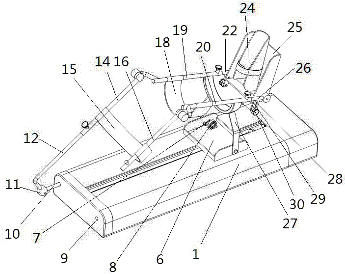
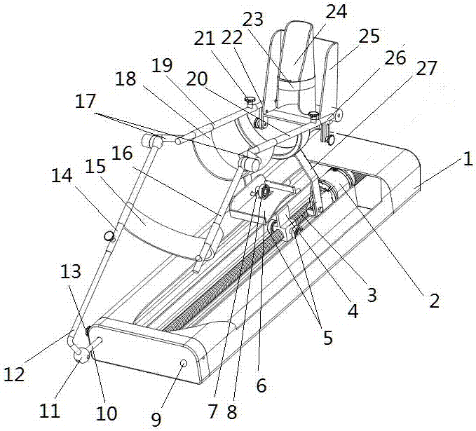
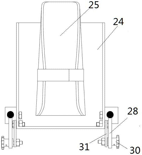
[0011] For further detailed explanation of the present invention in conjunction with the accompanying drawings, the front and rear directions in the present invention are defined as: the rear refers to the direction of the foot restraint device, the front refers to the direction of the two thigh support rods, and left and right are the actual left and right directions when facing forward. Each mark in the drawings is: 1: base; 2: motor; 3: lead screw; 4: nut; 5: bearing one; 6: fixed plate; 7: hinge shaft; 8: bearing two; 9: right socket; 10: Adjusting rod; 11: Universal joint; 12: L-shaped connecting rod; 13: Lock nut one; 14: Left thigh support rod; 15: Thigh support; 16: Right thigh support r...


PUM


Abstract

The invention discloses a lower limb joint training device which comprises a base and a linear movement mechanism. The linear movement mechanism is arranged on the lower portion of the lower limb joint training device, a fixing plate is connected onto a linear movement portion of the linear movement mechanism, a shank support frame is arranged above the fixing plate and is connected onto a support, the support is rotationally connected onto the fixing plate, a left brace rod of a foot tying device is connected with the shank support frame, two sides of a foot tying device frame are rotationally connected onto two support rods of the foot tying device, the foot tying device is arranged on the foot tying device frame, thigh support rods are rotationally connected with the front ends of shank support rods, an L-shaped connecting rod is connected with the front end of one of the two thigh support rods, the other end of the L-shaped connecting rod is connected onto a universal joint, and an adjusting rod is connected with the other end of the universal joint and is connected with the lower portion of the lower limb joint training device. The lower limb joint training device has the advantages of simple structure and low cost.

Description

technical field [0001] The invention relates to a rehabilitation medical training device, in particular to a lower limb joint training device in rehabilitation medical treatment, and belongs to the technical field of medical equipment. Background technique [0002] Injuries to the hip, knee, and ankle of the lower extremities are one of the common orthopedic diseases. In addition to healing the injured part during treatment, it is also necessary to perform corresponding functional training on the hip, knee, and ankle. Rehabilitation training equipment for hip joints, knee joints, and ankle joints has relatively single functions, and generally cannot treat hip joints, knee joints, and ankle joints at the same time, and the training range and angle cannot be adjusted, and the effect is not obvious after use. To meet the fixed-point position and diversification requirements, at present, it is generally a rehabilitation training robot that can simultaneously train the joints of ...

Claims


Application Information

Patent Timeline
IPC IPC(8): A61H1/02
CPCA61H1/0255A61H2205/102A61H2205/088
Inventor 崔建松张庆光郭宪魏
Owner ANYANG XIANGYU MEDICAL EQUIP
Learn More