Mechanical adjustment premix type gas burner and method

A gas burner and mechanical adjustment technology, which is applied in the direction of combustion method, burner, combustion type, etc., can solve the problems of excess auxiliary gas, insufficient combustion of gas, and deformation of the fire outlet, so as to reduce the consumption and improve the sintering quality.

Inactive Publication Date: 2017-09-22
乌鲁木齐九品芝麻信息科技有限公司
View PDF4 Cites 0 Cited by
  • Summary
  • Abstract
  • Description
  • Claims
  • Application Information

AI Technical Summary

Problems solved by technology

[0003] As far as the inventor knows, the current domestic combustion device used in the sintering process of refractory materials is diffusion combustion, and the commonly used diffusion combustion has several disadvantages in the combustion while the auxiliary gas and gas are mixed; Cause excess combustion gas, increase the temperature of the exhaust gas and increase the heat loss of the kiln
Second, due to poor mixing, the gas cannot be fully combusted, resulting in excess fuel, thus wasting fuel
The working method of the burner on the existing design combustion device is to sinter by the external flame under the condition of heat radiation, and at the same time, the highest temperature part is not on the sintered object on the kiln wall, and part of the heat energy is transferred by the inner kiln wall and the sintered object through radiation. It is not directly sintered by flame, so in the actual operation, the fire outlet of the kiln wall is particularly deformed due to sintering. In addition, the temperature inside the kiln wall is higher than the temperature of the sintered object, which is a waste of fuel

Method used


Image

  • Mechanical adjustment premix type gas burner and method

Examples


Embodiment Construction

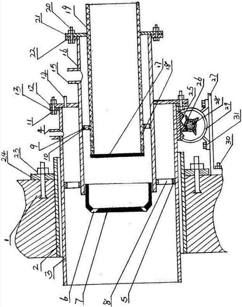
[0010] Such as figure 1 The specific embodiment of the mechanically adjusted premixed gas burner and the method of the invention shown in the figure is characterized in that a gas pipe 19 is provided, and a plug 17 is arranged at the front end of the gas pipe 19, and the front end of the gas pipe 19 is provided on the end close to the plug 17. There are a plurality of gas outlets 18, and the gas pipe 19 is provided with a second fixing bracket 9 near the gas outlet 18, and a plurality of gas injection holes 10 are uniformly arranged on the second fixing bracket 9, and a connecting plate is arranged at the tail end of the gas pipe 19- b21, the connecting plate-b21 is tightly connected with the flange-b22 fixed at the end of the mixing pipe 16 through the flange bolt-b20, the front end of the mixing pipe 16 is provided with a gas burner 7, and the gas burner 7 is provided with a mixed gas outlet 6, the end of the mixing tube 16 close to the gas burner 7 is provided with a first ...


PUM


Abstract

The invention provides a mechanical adjustment premix type gas burner and method. A plug 17 is arranged at the front end of a gas pipe 19. Multiple gas outlets 18 are formed in the end, close to the plug 17, of the front end of the gas pipe 19. A second fixed support 9 is arranged at the position, close to the gas outlet 18, of the gas pipe 19. A connection disc b21 is arranged at one end of the tail end of the gas pipe 19. A gas burner body 7 is arranged at the front end of a mixing pipe 16. A first fixed support 5 is arranged at the end, close to the gas burner body 7, of the mixing pipe 16. An auxiliary wind opening 15 is formed in the end, close to a flange plate b22, of the mixing pipe 16. A connection disc a12 is arranged at the end, close to the auxiliary wind opening 15, of the mixing pipe 16. A main wind opening 4 is formed in the end, close to a flange plate a13, of an adjustable air pipe 3. The front section of the adjustable air pipe 3 is sleeved with an air pipe 2. The air pipe 2 is fixed to a kiln wall 1 through expansion bolts 23 by means of a fastening steel plate 24 fixedly arranged on the tail section.

Description

[0001] This application is a divisional application of the invention patent application with the application number: 2013100465748, the invention name: mechanical adjustment premixed gas burner and method, and the application date: January 24, 2013. Technical field: [0002] The invention specifically relates to a mechanically regulated premixed gas burner and a method thereof, which belong to the technical field of kiln combustion and are suitable for the combustion application of refractory materials. Background technique: [0003] As far as the inventor knows, the combustion device used in the sintering process of refractory materials in China is diffusion combustion, and the commonly used diffusion combustion is that the gas-supporting gas and the gas are mixed while burning, and there are several disadvantages; It causes excess gas-supporting gas, increases the temperature of the exhaust gas, and increases the heat loss of the kiln. The second is that the gas cannot be ...

Claims


Application Information

Patent Timeline
Patent Type & Authority Applications(China)
IPC IPC(8): F23D14/02F23D14/62F27B9/36
CPCF23D14/02F23D14/62F23D2203/007F27B9/36F27M2003/04
Inventor 不公告发明人
Owner 乌鲁木齐九品芝麻信息科技有限公司
Why Eureka
Try Eureka