
Vibration reduction belt wheel

A technology of pulleys and pulleys, applied in belts/chains/gears, components with teeth, portable lifting devices, etc., can solve the problems of life loss of rubber layer, impact of pulley running accuracy and life, impact of pulley transmission accuracy, etc. , to avoid accelerated aging, improve smooth operation and reliability

Inactive Publication Date: 2017-09-22
ANHUI JIANGHUAI AUTOMOBILE GRP CORP LTD
View PDF9 Cites 1 Cited by
  • Summary
  • Abstract
  • Description
  • Claims
  • Application Information

AI Technical Summary

Problems solved by technology

[0004] The disadvantage of the above solution is that there is no axial and radial limit, which leads to the inability to effectively limit the radial force and axial movement of the belt, the transmission accuracy of the pulley is affected and the extreme working conditions are easily damaged
Specifically, since the belt needs to be tensioned, it will produce radial tension on the pulley, and the pulley using a common rubber layer will produce rubber compression along the direction of tension, and the inner and outer pulleys will not be concentric, which will affect the running accuracy and life of the pulley.
In addition, since each set of pulleys is not completely on the same plane after installation, the belt will generate axial tension on the pulley due to different flatness, causing the rubber layer to be subjected to additional force to cause life loss.

Method used


Image

  • Vibration reduction belt wheel
  • Vibration reduction belt wheel
  • Vibration reduction belt wheel

Examples


Embodiment Construction

[0019] The embodiments described below by referring to the figures are exemplary only for explaining the present invention and should not be construed as limiting the present invention.

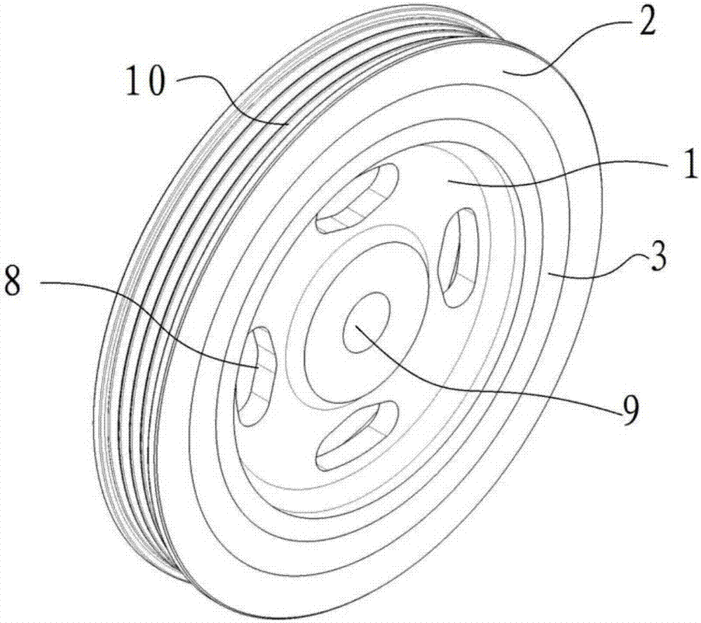
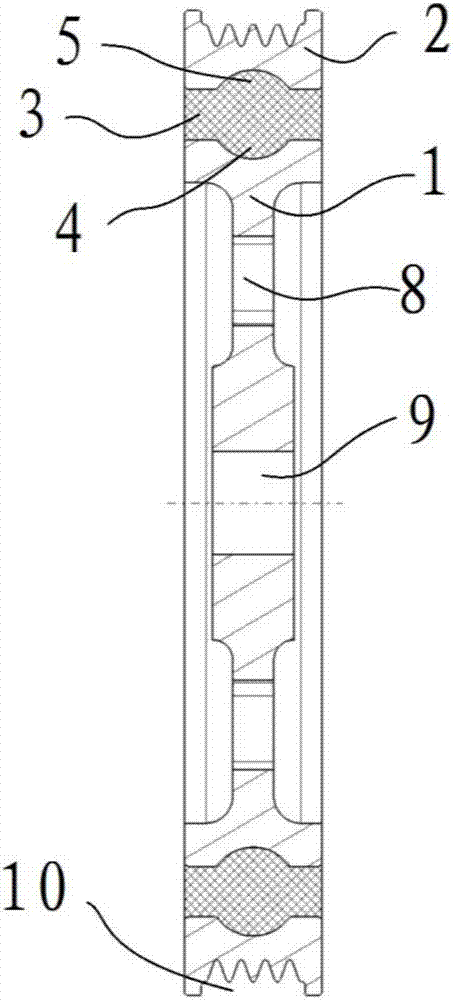
[0020] like Figure 1 to Figure 5 As shown, the embodiment of the present invention provides a vibration-damping pulley, including an inner pulley 1 provided with a shaft hole 9, an outer pulley 2 provided with a belt groove 10 on the outer circumference, and an outer pulley 2 arranged on the inner belt The rubber layer 3 between the wheel 1 and the outer pulley 2, the inner pulley 1, the outer pulley 2 and the rubber layer 3 are coaxially arranged, the shaft hole 9 is provided with a keyway, and the inner pulley 1 It is fixedly connected with the crankshaft in the way of key and keyway, the belt loop is set in the belt groove 10, and the power is output to the external device. The outer peripheral surface of the inner pulley 1 is provided with a first arc-shaped groove 4. The inner circumfe...


PUM


Abstract

The invention discloses a vibration reduction belt wheel. The vibration reduction belt wheel comprises an inner belt wheel with a shaft hole, an outer belt wheel provided with a belt groove in the outer circumferential face annularly and a rubber layer arranged between the inner belt wheel and the outer belt wheel, a first arc-shaped groove is formed in the outer circumferential face of the inner belt wheel annularly, a second arc-shaped groove is formed in the inner circumferential face of the outer belt wheel, the first arc-shaped groove and the second arc-shaped groove are oppositely arranged to form a rolling way, and multiple balls are assembled in the rolling way. Compared with the prior art, the rolling way with the arc-shaped cross section is designed between the outer belt wheel and the inner belt wheel, the multiple balls are assembled in the rolling way, the runner layer equivalently serves as a holding support of the balls, and therefore the outer belt wheel and the inner belt wheel have rigid axial and radial limiting, radial loads and axial loads are borne at the same time, radial and axial displacement of the inner belt wheel and the outer belt wheel is effectively limited, accelerated aging caused by transmission errors and extra stress of rubber is avoided, and the running stability and reliability are improved.

Description

technical field [0001] The invention relates to the field of automobile engines, in particular to a vibration-damping pulley. Background technique [0002] Torque output fluctuations caused by the structure and working environment of the engine or other power output devices are called torsional vibrations. Torsional vibrations cause torque fluctuations in other corresponding components of the power train, producing vibrations tangential to the axis. If the vibration energy is high and coincides with the natural frequency of other components of the drive chain, serious resonance will occur, resulting in poor noise and vibration of the vehicle. [0003] Usually, damping is added to the pulley at the end of the crankshaft to attenuate the torsional vibration in its characteristic frequency range. The outer pulley has a certain thickness and quality as a mass block, the inner pulley is an integral flange and crankshaft assembly, and a certain thickness of rubber is vulcanized ...

Claims


Application Information

Patent Timeline
Patent Type & Authority Applications(China)
IPC IPC(8): F16H55/48
CPCF16H55/48F16H2055/366
Inventor 秦政委申露露石磊磊彭宜爱
Owner ANHUI JIANGHUAI AUTOMOBILE GRP CORP LTD
Learn More