
Forming method for shell of airplane cover

A molding method and machine cover technology, applied in the field of carbon fiber products, can solve the problems of unqualified finished product performance, affecting the uniformity of product density, and difficulty in laying carbon fiber cloth evenly and evenly, so as to ensure the performance of finished products, uniform distribution of glue injection points, The effect of ensuring uniformity

Inactive Publication Date: 2017-09-22
NINGBO CITY EPL MOLD & PLASTIC
View PDF3 Cites 5 Cited by
  • Summary
  • Abstract
  • Description
  • Claims
  • Application Information

AI Technical Summary

Problems solved by technology

But this molding die of prior art has following shortcoming: because a plurality of inserts are provided with in the molding die, and usually these inserts are all arranged on one side of cavity, therefore, when molding die clamping, these The inserts are easy to touch the carbon fiber cloth and make the carbon fiber cloth move. In this way, it is difficult to lay the carbon fiber cloth evenly and evenly, which will affect the uniformity of the product density and lead to unqualified performance of the finished product

Method used


Image

  • Forming method for shell of airplane cover
  • Forming method for shell of airplane cover
  • Forming method for shell of airplane cover

Examples


Embodiment Construction

[0026] The present invention will be described in further detail below in conjunction with the accompanying drawings and specific embodiments.

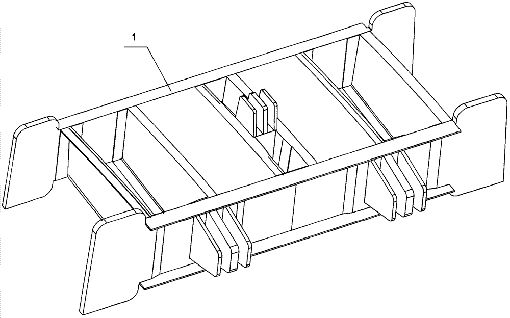
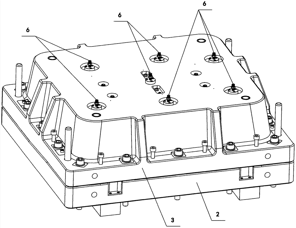
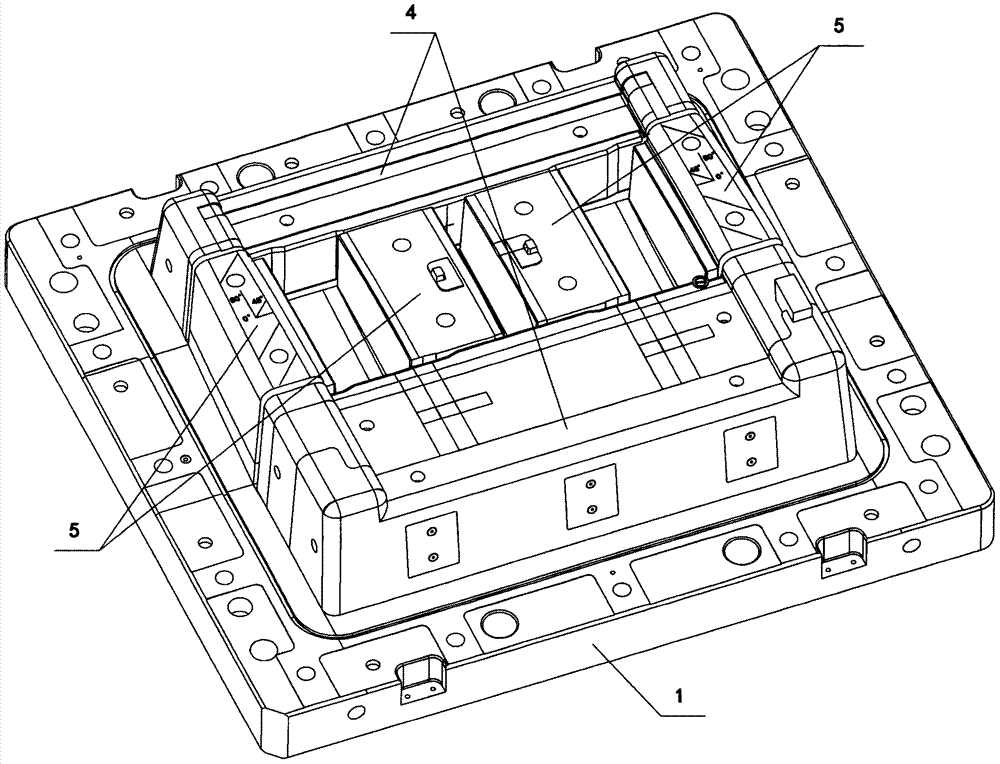
[0027] Depend on Figure 1 to Figure 6 As can be seen from the structural representation of the molding die used in the molding method of the aircraft cover shell of the present invention shown, it comprises the following steps:

[0028] 1) Make a special forming mold, the forming mold includes an upper mold 3, a lower mold 2 and an inclined roof mechanism, the upper mold and the lower mold form a product cavity after the mold is closed, and the forming slider 4 and the upper core of the product cavity are formed. The inserts 5 can be detachably connected to the lower mold 2, the inclined top mechanism is set in the upper mold 3, and the inclined top slider 7 is located on the surface of the cavity; the forming mold is provided with seven injection holes connected with the product cavity. point 6, and the seven glue injection points ...


PUM


Abstract

The invention discloses a forming method for a shell of an airplane cover. The forming method comprises the steps that (1) a special forming mould is manufactured; (2) carbon fiber cloths are laid; (3) mould compounding and glue injecting are conducted; (4) vacuumizing operation is conducted while glue is injected; (5) solidification and pressure maintaining are conducted; and (6) a product is demoulded and taken out. By adopting the method, the stability of the positions of the carbon fiber cloths is guaranteed, the density uniformity of the product is guaranteed accordingly, and it is guaranteed that performance of the finished product is qualified.

Description

technical field [0001] The invention relates to the technical field of carbon fiber products, in particular to a forming method for an aircraft cover shell of a helicopter engine. Background technique [0002] The production requirements of aviation parts are very high. It is necessary to ensure its strength and reduce its weight as much as possible. Therefore, the material requirements for aviation parts are relatively high, and the most commonly used carbon fiber materials are used to make carbon fiber materials. This is because carbon fibers have a weight ratio. Aluminum is light, but its strength is higher than steel, and it has the advantages of corrosion resistance, high temperature resistance, and high modulus. At present, there are many ways to manufacture carbon fiber products, and the most suitable method for making aviation parts is the molding method. This method is to put the carbon fiber material that has been pre-impregnated with resin into the metal forming m...

Claims


Application Information

Patent Timeline
Patent Type & Authority Applications(China)
IPC IPC(8): B29C70/36B29C70/54B29C33/00B29C33/12B29L31/30
CPCB29C33/00B29C33/12B29C70/36B29C70/54B29C70/541B29L2031/3088
Inventor 王少峰彭河王家利
Owner NINGBO CITY EPL MOLD & PLASTIC
Learn More