
Efficient building dust removal device

A dust removal device and construction technology, applied in the direction of combination device, separation device, liquid separation agent, etc., can solve the problems of dust pollution, dust flying, large area of ​​water on the construction site, etc., to increase the dust content and improve the dust removal effect , the effect of improving safety

Inactive Publication Date: 2017-09-22
樊一
View PDF7 Cites 13 Cited by
  • Summary
  • Abstract
  • Description
  • Claims
  • Application Information

AI Technical Summary

Problems solved by technology

[0002] With the development of society, China's real estate industry has developed rapidly. At the same time as the real estate industry develops, the construction site will generally cause dust and serious pollution during the construction process, especially on the temporary roads at the construction site. , the frequent entry and exit of construction vehicles makes the dust pollution of the construction site even more serious. The current construction site generally adopts simple artificial watering to reduce dust. This method often causes large areas of water on some grounds, while other places cannot be sprinkled with water. , the sprinkling of water is uneven, resulting in a waste of water resources, and some equipment such as ventilators and ventilation fans are used for dust removal. The dust removal effect is good at the beginning, but as the dust accumulates on the filter screen of the adsorption device, the adsorption effect will become worse and worse, making Existing equipment is difficult to continue to work during building construction

Method used


Image

  • Efficient building dust removal device
  • Efficient building dust removal device
  • Efficient building dust removal device

Examples


Embodiment Construction

[0017] The following will clearly and completely describe the technical solutions in the embodiments of the present invention with reference to the accompanying drawings in the embodiments of the present invention. Obviously, the described embodiments are only some, not all, embodiments of the present invention. Based on the embodiments of the present invention, all other embodiments obtained by persons of ordinary skill in the art without making creative efforts belong to the protection scope of the present invention.

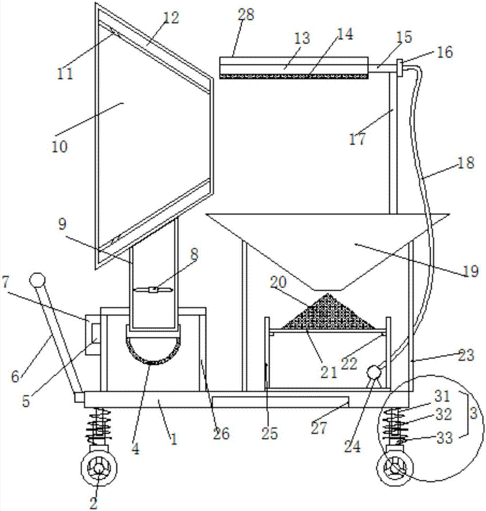
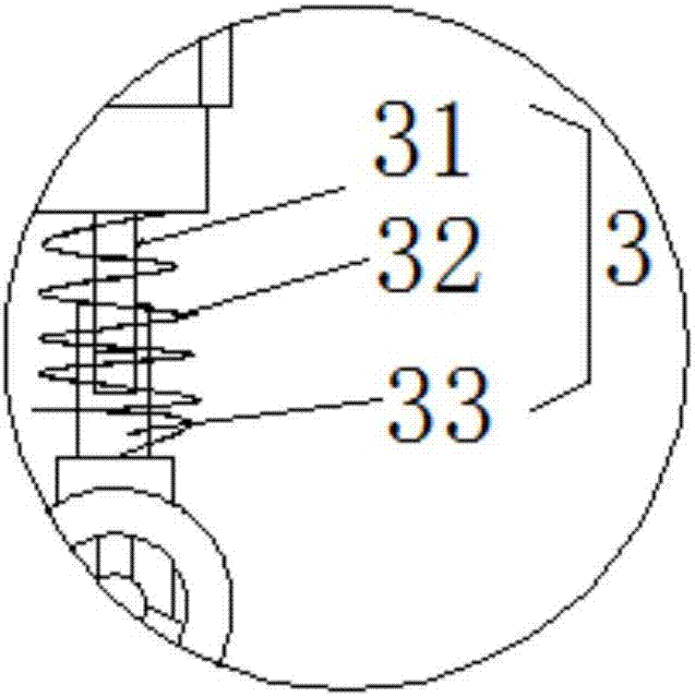
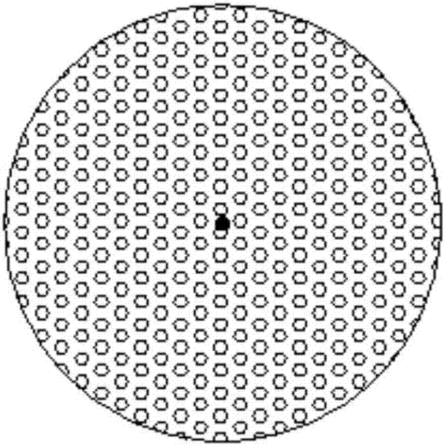
[0018] see Figure 1~3 , in an embodiment of the present invention, a high-efficiency building dust removal device includes a base 1 and a conical cover 10, legs 3 are provided on both sides of the lower end of the base 1, and rollers 2 are provided at the lower end of the legs 3 to facilitate the handling of the device. 2 is a self-locking roller, and the supporting leg 3 includes a telescopic rod 31, a telescopic sleeve 32 and a buffer spring 33. The upper e...


PUM


Abstract

The invention discloses an efficient building dust removal device. The efficient building dust removal device comprises a base and a conical cover, wherein support legs are arranged on two sides of the lower end of the base; a rolling wheel is arranged at the lower end of each support leg; each support leg comprises a telescopic rod, a telescopic sleeve and a buffering spring; the upper end of each telescopic rod is fixedly connected with the base; the lower end of each telescopic rod is slidably sleeved with a telescopic sleeve; the telescopic sleeves are fixedly connected with the base through the buffering springs; the buffering springs are used for absorbing vibration generated by the device. The efficient building dust removal device is simple and reasonable in structure; airflow flowing from left to right is formed in the conical cover, so that the content of dust in the unit space is increased; the dust removal effect of the device is greatly improved; furthermore, fan blades are eliminated in the conical cover, so that the safety of the device is improved; meanwhile, the device is also capable of achieving cyclic utilization of the water resource; the effect of saving water is achieved; in addition, the device is capable of achieving self power supply by using solar energy, so that the effect of saving energy and power can be achieved; the efficient building dust removal device is high in practicability.

Description

technical field [0001] The invention relates to the technical field of building equipment, in particular to a high-efficiency building dust removal device. Background technique [0002] With the development of society, China's real estate industry has developed rapidly. At the same time as the real estate industry develops, the construction site will generally cause dust and serious pollution during the construction process, especially on the temporary roads at the construction site. , the frequent entry and exit of construction vehicles makes the dust pollution of the construction site more serious. The current construction site generally adopts simple artificial watering to reduce dust. This method often causes large areas of water on some grounds, while other places cannot be sprinkled with water. , the sprinkling of water is uneven, resulting in waste of water resources, and some equipment such as ventilators and ventilation fans are used to remove dust. The dust removal...

Claims


Application Information

Patent Timeline
Patent Type & Authority Applications(China)
IPC IPC(8): B01D50/00B01D47/06
CPCB01D47/06B01D2247/04B01D50/60
Inventor 樊一
Owner 樊一
Learn More