
Expandable embroidering machine presser foot

An embroidery machine and presser foot technology, applied in the field of embroidery machines, can solve problems affecting embroidery quality and embroidery defects, and achieve the effects of facilitating cleaning and maintenance, reducing the possibility of wrinkles, and increasing production efficiency

Inactive Publication Date: 2017-09-19
杨芝燕
View PDF0 Cites 1 Cited by
  • Summary
  • Abstract
  • Description
  • Claims
  • Application Information

AI Technical Summary

Problems solved by technology

When embroidery just started to break away from manual embroidery, the so-called embroidery machine at that time was not a real embroidery machine, because the embroidery machine at that time used a traditional sewing machine, replaced with a bottom plate with a small round hole, and the sewing machine needle kept going. Going in and out up and down, plus holding the cloth taut with the embroidery frame, moving back and forth, in fact, this so-called embroidery machine is still a kind of hand embroidery, and the current embroidery machine with the development of technology It is also becoming more and more automatic, but the embroidery machine is equipped with a presser foot that matches the embroidery needle, but the presser foot is generally of a fixed style, and its pressing part is relatively small. When the embroidery is moving, it may be caused by wrinkles. The cause of the embroidery is flawed, which affects the quality of the embroidery

Method used


Image

  • Expandable embroidering machine presser foot
  • Expandable embroidering machine presser foot
  • Expandable embroidering machine presser foot

Examples


Embodiment Construction

[0015] The following will clearly and completely describe the technical solutions in the embodiments of the present invention with reference to the accompanying drawings in the embodiments of the present invention. Obviously, the described embodiments are only some, not all, embodiments of the present invention.

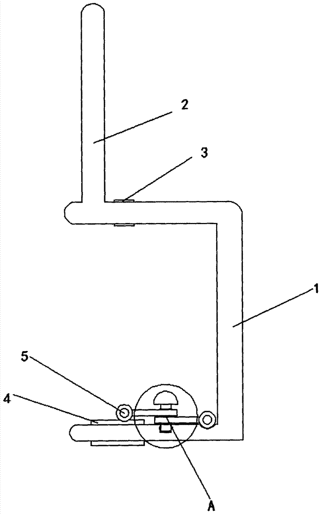
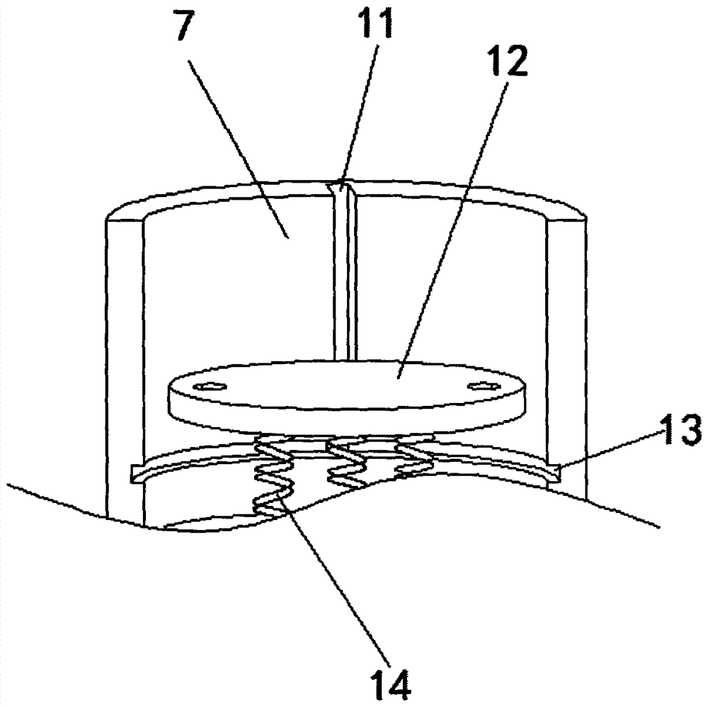
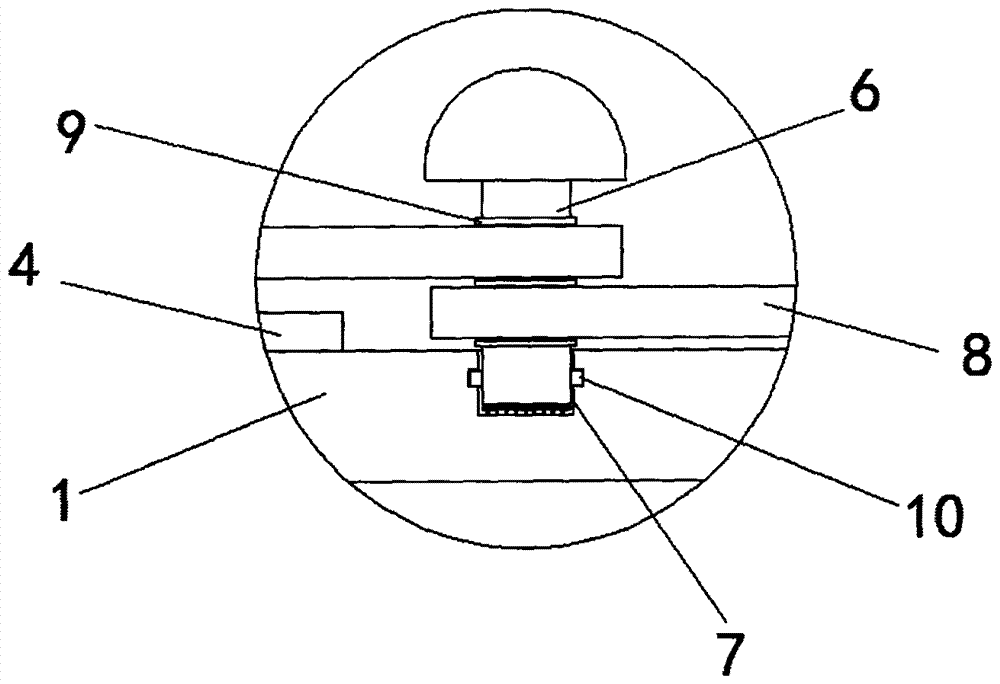
[0016] refer to Figure 1-3 , an expandable embroidery machine presser foot, comprising a U-shaped bar 1, the upper end of the U-shaped bar 1 close to the U-shaped opening is provided with a connecting rod 2, and the upper end of the U-shaped bar 1 close to the connecting bar 2 is provided with a second A socket 3, and the lower end of the U-shaped bar 1 is provided with a second socket 4 corresponding to the first socket 3, and the inner walls of the first socket 3 and the second socket 4 are provided with plastic protective sleeves, and the second socket 4 The U-shaped bar 1 on the same side is provided with a groove 7, the bottom of the groove 7 is provided with a...


PUM


Abstract

The invention discloses an expandable embroidering machine presser foot. The expandable embroidering machine presser foot comprises a U-shaped rod, wherein a connecting rod is arranged at the upper end of one side, close to a U-shaped opening, of the U-shaped rod; a first inserting opening is formed in the upper end of one side, close to the connecting rod, of the U-shaped rod; a second inserting opening, which corresponds to the first inserting opening, is formed in the lower end of the U-shaped rod; a groove is formed in the U-shaped rod located on the same side of the second inserting opening; a bottom plate is arranged at the bottom of the groove; the bottom plate and a bottom wall of the groove are connected through a plurality of springs; a vertical sliding groove is formed in a side wall of the groove; a fixed rod is arranged at the upper side of the bottom plate; a side wall of the fixed rod is provided with a sliding block matched with the vertical sliding groove; and an annular groove communicated with the vertical sliding groove is formed in the side wall of the groove. The expandable embroidering machine presser foot disclosed by the invention has a simple structure; the expandable embroidering machine presser foot can be used for carrying out embroidering work very well, and the fixed rod and parts matched with the fixed rod are arranged, so that the possibility that a product to be embroidered has folds can be reduced, and the efficiency of production is increased.

Description

technical field [0001] The invention relates to the technical field of embroidery machines, in particular to an expandable embroidery machine presser foot. Background technique [0002] Embroidery machines, embroidery machines, or embroidery machines. When embroidery just started to break away from manual embroidery, the so-called embroidery machine at that time was not a real embroidery machine, because the embroidery machine at that time used a traditional sewing machine, replaced with a bottom plate with a small round hole, and the sewing machine needle kept going. Going in and out up and down, plus holding the cloth taut with the embroidery frame, moving back and forth, in fact, this so-called embroidery machine is still a kind of hand embroidery, and the current embroidery machine with the development of technology It is also becoming more and more automatic, but the embroidery machine is equipped with a presser foot that matches the embroidery needle, but the presser ...

Claims


Application Information

Patent Timeline
Patent Type & Authority Applications(China)
IPC IPC(8): D05C9/20
CPCD05C9/20
Inventor 杨芝燕
Owner 杨芝燕
Learn More