
Paint spraying device

A paint room and component technology, applied in the field of painting equipment and painting tools, can solve the problems of slow solidification of paint surface and uneven painting, and achieve the effects of rapid heating, solidification and accurate coloring.

Pending Publication Date: 2017-09-19
王雪琴
View PDF6 Cites 3 Cited by
  • Summary
  • Abstract
  • Description
  • Claims
  • Application Information

AI Technical Summary

Problems solved by technology

However, the existing technology has the shortcomings of uneven painting and slow solidification of the paint surface. Therefore, the improvement of the painting process is an important direction to improve the production efficiency and product quality of enterprises.

Method used


Image

  • Paint spraying device
  • Paint spraying device

Examples


Embodiment 1

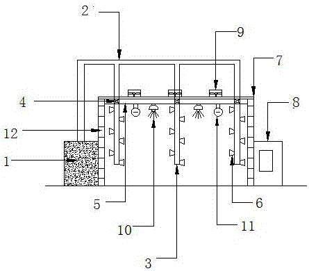
[0013] Embodiment 1: see Figure 1-Figure 2 , a paint spraying device, the paint spraying device includes a paint spraying assembly, a heating exhaust assembly, a control assembly and a shed body assembly; the paint spraying assembly is partially located in the shed body assembly, and the rest is located outside the shed body assembly; the heating exhaust The wind assembly is located inside the shed body assembly; the control assembly includes a temperature sensor and a paint room control room, the temperature sensor is arranged in the shed body assembly, the paint room control room is arranged outside the shed body assembly, and the shed body assembly It includes a heat-insulation shed body 12 and a heat-insulation shed roof 7 , said heat-insulation shed roof is arranged on the heat-insulation shed body 12 . The design structure is simple and clear, and the components are closely connected without interfering with each other. The required parts are easy to replace and easy to...

Embodiment 2

[0014] Example 2: see Figure 1-Figure 2 , as an improvement of the present invention, the painting component includes a paint mixing room 1, a paint delivery pipeline 2, a movable column 3, a pulley 4, a pulley running track 5 and a paint mist nozzle 6, and the paint mixing room passes through The paint delivery pipeline is connected to the top of the movable pipe column; the movable pipe column is fixed at the lower end of the pulley, and the pulley is set on the pulley running track, and the pulley running track is fixed under the heat insulation roof, and the paint The mist nozzles are arranged on the side wall of the movable column. The advantage of this design is that the position of the required painting workpiece in the house can be precisely positioned by controlling the movable column. According to the size of the workpiece to be painted, the distribution position of the movable pipe column is changed, and the paint mist nozzle is accurately aimed at the surface to ...

Embodiment 3

[0015] Embodiment 3: see Figure 1-Figure 2 , as an improvement of the present invention, the heating exhaust assembly includes an exhaust fan 9 and an infrared oven lamp 10; the exhaust fan 9 is installed on the heat insulation roof 7; the infrared oven lamp is hoisted below the heat insulation roof. Infrared oven lamp is used as the heating source, which not only heats up quickly, but also has low energy consumption, which further makes this product meet the national energy-saving and emission-reduction requirements.


PUM


Abstract

The invention relates to a paint spraying device. The paint spraying device comprises a paint spraying assembly, a heating air exhaustion assembly, a control assembly and a shelter body assembly, wherein the local part of the paint spraying assembly is positioned in the shelter body assembly and the other parts of the paint spraying assembly are positioned outside the shelter body assembly; the heating air exhaustion assembly is positioned on the inner side of the shelter body assembly; the control assembly comprises a temperature sensor and an oil paint house control room; the temperature sensor is arranged in the shelter body assembly; the oil paint house control room is arranged outside the shelter body assembly; the shelter body assembly comprises a heat insulating shelter body and a heat insulating shelter top; and the heat insulating shelter top is arranged on the heat insulating shelter body. According to the technical scheme, the paint spraying device is high in heating speed, constant in temperature and good in sealing property; in a spraying process, the pollution to a paint surface cannot be easily caused by the external dust. According to the design, a movable pipe column is controlled to precisely position the position of workpieces requiring paint spraying in the room, a paint mist nozzle can accurately align to the surface requiring paint spraying, so that the quick and uniform paint spraying operation can be carried out.

Description

technical field [0001] The invention relates to a painting tool, in particular to a painting device, belonging to the technical field of mechanical structures. Background technique [0002] Spray paint is an indispensable and important part of modern industrial production. Especially in the field of machinery manufacturing, the quality of the painting process is an important criterion for determining the final quality of the product. However, the existing technology has the disadvantages of uneven spraying and slow solidification of the paint surface, so the improvement of the painting process is an important direction for improving the production efficiency and product quality of enterprises. How to evenly spray paint on the surface of the workpiece and quickly dry the paint surface has become a difficult problem in front of people. Contents of the invention [0003] The present invention aims at the technical problems existing in the prior art, and provides a painting ...

Claims


Application Information

Patent Timeline
Patent Type & Authority Applications(China)
IPC IPC(8): B05B15/12B05B15/08B05D3/02B05D3/04
CPCB05D3/0263B05D3/0406
Inventor 王雪琴
Owner 王雪琴
Learn More