Worm gear skull annular rod combined external fixing bracket

A worm gear and external fixation technology, applied in the field of medical equipment, can solve the problems of complex structure, small transmission ratio, complicated operation, etc., and achieve the effects of simple structure, accurate and reliable action, and convenient adjustment.

Pending Publication Date: 2017-09-19
TIANJIN XINZHONG MEDICAL DEVICES
View PDF8 Cites 4 Cited by
  • Summary
  • Abstract
  • Description
  • Claims
  • Application Information

AI Technical Summary

Problems solved by technology

At present, most of the orthopedic ring-rod combination external fixation brackets commonly used in domestic and foreign medical markets are combined with a general-purpose ring and threaded rod. Recently, similar products that have applied for patents use straight-toothed threads or ordinary gear transmission structures to move bone blocks. There are the following disadvantages: 1. The skull cannot be accurately and slowly slid and fixed during the bone transfer process; 2. The structure of the general-purpose instrument is complex and the operation of the combination is cumbersome; 3. The screw drive or ordinary spur gear drive will have the disadvantage of complicated operation. Especially in the transmission of ordinary spur gears, the transmission ratio is too small, which causes the disadvantages of the skull bone moving too fast.

Method used


Image

  • Worm gear skull annular rod combined external fixing bracket
  • Worm gear skull annular rod combined external fixing bracket
  • Worm gear skull annular rod combined external fixing bracket

Examples


Embodiment Construction

[0014] The following will clearly and completely describe the technical solutions in the embodiments of the present invention with reference to the accompanying drawings in the embodiments of the present invention. Obviously, the described embodiments are only some, not all, embodiments of the present invention. Based on the embodiments of the present invention, all other embodiments obtained by persons of ordinary skill in the art without making creative efforts belong to the protection scope of the present invention.

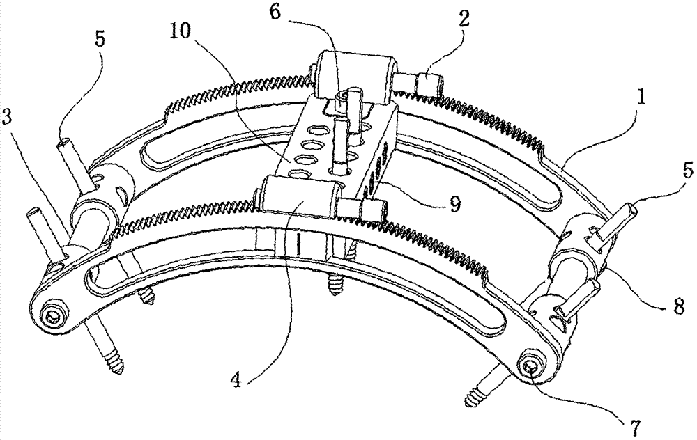
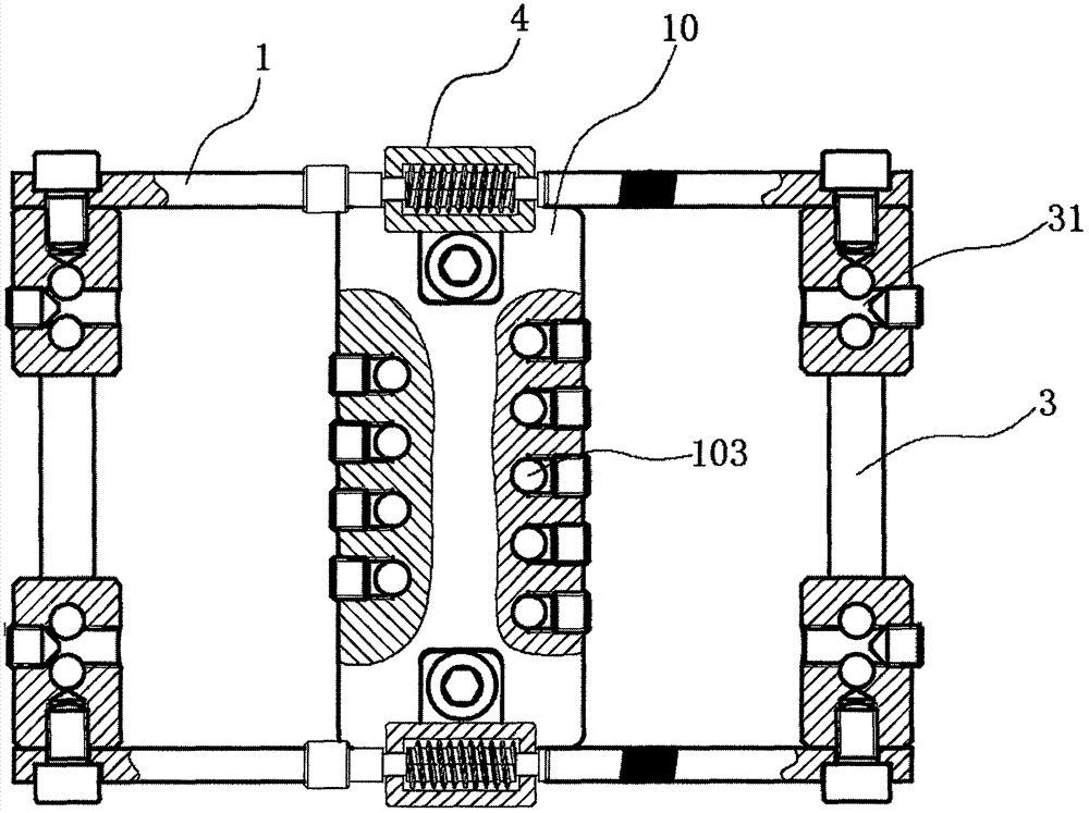
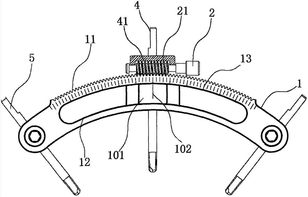
[0015] see Figure 1-3 , the present invention provides a technical solution: a worm gear and worm skull ring rod combined external fixation bracket, including a slider 10, the front and rear ends of the slider 10 are movably installed with a worm gear side plate 1, and the top of the worm gear side plate 1 The middle part is provided with worm gear teeth 11, and the middle part of the worm wheel side plate 1 is provided with an arc-shaped sliding groove 12, a...


PUM


Abstract

The invention discloses a worm gear skull annular rod combined external fixing bracket which comprises a sliding block, wherein worm gear lateral plates are movably arranged at front and rear ends of the sliding block; worm gear teeth are arranged on the middle parts of the top ends of the worm gear lateral plates; arc-shaped sliding slots are formed in the middle parts of the worm gear lateral plates; scale marks are arranged on the upper sides of the front and rear side walls of the worm gear lateral plates; horizontal connecting rods are fixedly arranged at left and right ends of the worm gear lateral plates through connecting bolts; bone pinholes are formed in the front and rear sides of a jackscrew hole and an upper end face of the sliding block; a bone pin is in penetrated connection with the bone pinholes; a free skull bone block is driven by the bone pin fixed on free skull to move bone along a certain radian; worm support bases are fixedly arranged on front and rear sides of the top end of the sliding block; worm teeth are arranged on a side wall of the left end of a worm bolt; guiding blocks are arranged on the middle parts of the front and rear ends of the sliding block; the marking lines are arranged on the middle parts of the external ends of the guiding blocks; the marking lines are corresponding to the scale marks; the adjusting angle can be accurately controlled.

Description

technical field [0001] The invention relates to the technical field of medical devices, in particular to a worm gear and worm skull ring rod combination external fixation bracket. Background technique [0002] Skull fractures or skull defects caused by craniotomy are generally modified clinically with heterogeneous biological or metal materials, and this repair has brought many disadvantages, such as: foreign body rejection, foreign body severe infection, etc. , Russia has already had this literature and clinical data that it is a very effective operation to use external fixator bone transfer to repair bone defect or skull fixation; since it is in the skull part, it requires professional orthopedic instruments for fixation and bone transfer , to help the recovery and healing of defective bones as soon as possible, the worm gear and worm skull ring rod combination external fixation bracket is a professional medical device used in clinical surgery. At present, most of the ort...

Claims


Application Information

Patent Timeline
IPC IPC(8): A61B17/60A61B17/66
CPCA61B17/60A61B17/66A61B2017/603
Inventor 姚爱民李刚谢庆平方启龙于德才张伟
Owner TIANJIN XINZHONG MEDICAL DEVICES
Why Eureka
Try Eureka