A rapid lifting spreader for concrete prefabricated box girder

A technology of concrete and box girder, applied in the direction of load hanging components, transportation and packaging, can solve problems such as difficulty, achieve the effects of less damage, improved hoisting safety, and convenient operation

Inactive Publication Date: 2018-05-18
YANGTZE UNIVERSITY
View PDF6 Cites 0 Cited by
  • Summary
  • Abstract
  • Description
  • Claims
  • Application Information

AI Technical Summary

Problems solved by technology

[0006] The invention has ingenious structure and convenient operation, which not only solves the problem that it is difficult to place steel wire ropes or other lifting tools on the bottom of the concrete prefabricated box girder before hoisting, but also improves the safety of hoisting, and uses the side of the concrete prefabricated box girder as the Bearing surface, less damage to concrete prefabricated box girder

Method used


Image

  • A rapid lifting spreader for concrete prefabricated box girder
  • A rapid lifting spreader for concrete prefabricated box girder
  • A rapid lifting spreader for concrete prefabricated box girder

Examples


Embodiment Construction

[0012] The specific implementation manners of the present invention will be described in further detail below in conjunction with the accompanying drawings.

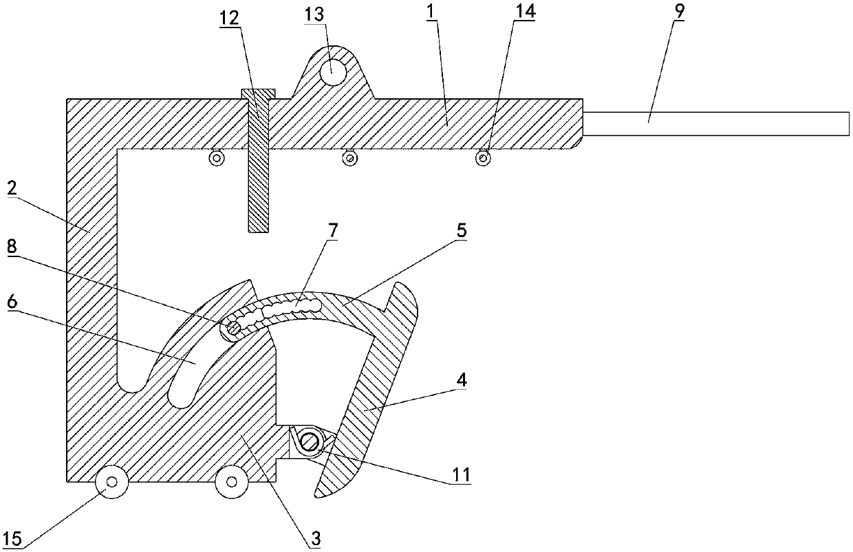
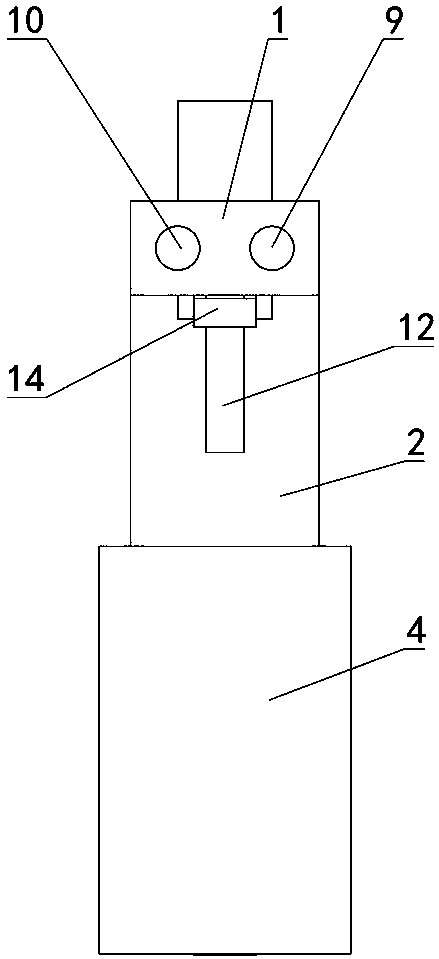
[0013] Depend on Figure 1 to Figure 5 Given, the present invention comprises crossbeam 1, and one end of crossbeam 1 is equipped with vertical beam 2 placed below crossbeam 1, and the lower end of vertical beam 2 is equipped with connection block 3, and one side of connection block 3 is equipped with and places below crossbeam 1. Extrude plate 4, the bottom of extrude plate 4 is hinged with connection block 3 through hinge shaft, and the upper part of extrude plate 4 is equipped with arc-shaped positioning bar 5, and connecting block 3 is provided with the circle that matches with position bar 5. The arc-shaped chute 6, the positioning rod 5 is placed in the chute 6, forming a structure in which the positioning rod 5 slides in the chute 6 when the extrusion plate 4 rotates on the hinge shaft;

[0014] The positioning b...


PUM


Abstract

The invention relates to a quick lifting tool for concrete precast box beams. The tool comprises a cross beam; a vertical beam positioned under the cross beam is mounted at one end of the cross beam; a connecting block is mounted at the lower end of the vertical beam; an extrusion plate positioned below the cross beam is mounted on one side of the connecting block; the lower part of the extrusion plate is hinged to the connecting block by an articulated shaft; an arc positioning rod is mounted at the upper part of the extrusion plate; the connecting block is provided with an arc sliding chute matched with the positioning rod; the positioning rod is positioned in the sliding chute, and is provided with a positioning toothed groove; the positioning toothed groove consists of multiple longitudinal through holes distributed in the radian direction of the positioning rod; and the connecting block is provided with a locking pin inserted in the corresponding longitudinal through hole. The tool is skilful in structure and convenient in operation, solves the problem of difficult placement of steel wire ropes or other lifters at the bottoms of the concrete precast box beams before lifting of the concrete precast box beams, and meanwhile, improves the lifting safety; and side surfaces of the concrete precast box beams are used as bearing surfaces, so that the damage to the concrete precast box beams is lower.

Description

technical field [0001] The invention relates to the field of hoisting of prefabricated concrete box girders, in particular to a rapid hoisting sling for prefabricated concrete box girders. Background technique [0002] When the concrete prefabricated box girder is hoisted, because the concrete prefabricated box girder is large and difficult to fix, it is usually bound with steel wire ropes and then lifted by hoisting equipment. The premise of this hoisting method is that there must be enough space between the prefabricated concrete box girder and the ground for the wire rope to pass through, otherwise it is very difficult to bind the prefabricated concrete box girder; Shaking is inevitable, the steel wire rope and the concrete prefabricated box girder are squeezed, slid, and misplaced, and the contact area between the steel wire rope and the concrete prefabricated box girder is small, and the pressure is too concentrated, which can easily cause damage to the concrete prefabr...

Claims


Application Information

Patent Timeline
Patent Type & Authority Patents(China)
IPC IPC(8): B66C1/44
CPCB66C1/44
Inventor 陈誉何康
Owner YANGTZE UNIVERSITY
Why Eureka
Try Eureka