A new energy vehicle charging device

A new energy vehicle and charging device technology, applied in electric vehicle charging technology, charging stations, electric vehicles, etc., can solve the problems of no protection device, electric shock, and shortening of the service life of charging wires, and achieve increased service life and safety protection. Good, easy to operate effect

Inactive Publication Date: 2018-10-16
PUJIANG ZHIYIN TECH CO LTD
View PDF6 Cites 0 Cited by
  • Summary
  • Abstract
  • Description
  • Claims
  • Application Information

AI Technical Summary

Problems solved by technology

[0003] The charging device is an important basic supporting charging facility for electric vehicles. The use process of the charging device is very similar to the refueling process of the car. During the charging operation of the electric vehicle, the operator needs to remove the charging gun from the charging device and connect it with the charging device of the electric vehicle. Hole connection, after the charging is finished, the operator should arrange the charging wires, and then put the charging gun head back into the charging device, but the charging wire has a certain length, which brings great inconvenience to the user when it is put back. In addition, If the charging wire is not retracted and exposed to the outside of the charging device, when the charging device is not in use, the charging wire is placed next to the charging device. When the charging wire is scattered in an improper position, there is a risk of the charging wire being trampled by people or being run over by a car. As a result, the outer insulation of the charging wire will be damaged, resulting in a decrease in the service life of the charging wire and poor safety protection; in addition, when the traditional charging gun is placed on the charging device, it is always in a power-on state, and there is no protection device for the charging gun. If children or other non-operators take it at will, it will cause electric shock and other accidents.

Method used


Image

  • A new energy vehicle charging device
  • A new energy vehicle charging device
  • A new energy vehicle charging device

Examples


Embodiment Construction

[0023] The preferred embodiments of the present invention will be described in detail below in conjunction with the accompanying drawings, so that the advantages and features of the present invention can be more easily understood by those skilled in the art, so as to define the protection scope of the present invention more clearly.

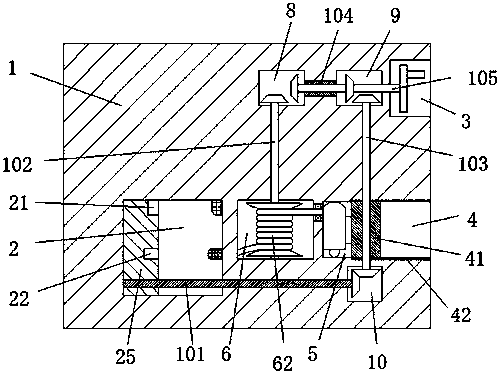
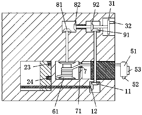
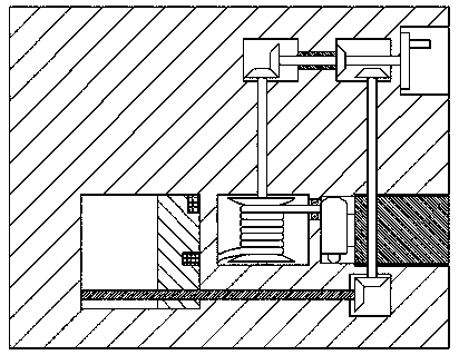
[0024] refer to Figure 1-7A new energy vehicle charging device shown includes a pile body 1, and the pile body 1 is provided with a power connection chamber 2, a first transmission chamber 8, a second transmission chamber 9, a third transmission chamber 10 and a wire receiving chamber 6. The right end of the pile body 1 is provided with an operation chamber 3 and a closed chamber 4 with an opening facing the right. The left end of the closed chamber 4 is connected with a charging gun placement chamber 5. The sliding block 25, the upper power supply block 23 and the lower power supply block 24 are arranged on the right end wall of the electric co...


PUM


Abstract

The invention discloses a charging device for a new energy vehicle, which comprises a pile body. The pile body is provided with a power connection cavity, a first transmission cavity, a second transmission cavity, a third transmission cavity and a wire take-up cavity. The right end of the pile body There is an operation cavity with an opening facing the right and a closed cavity on the surface. The left end of the closed cavity is connected with a charging gun placement cavity. An upper power supply block and a lower power supply block are provided, and the right end surface of the sliding block is provided with an upper connection hole cooperating with the upper power supply block and a lower connection hole cooperating with the lower power supply block; the present invention The structure is simple, and it can better realize the charging wire take-up and unwinding work, avoiding the charging wire being exposed to the outside of the charging device and being damaged, and the closing and opening of the charging gun placement cavity can be selectively controlled by operating the hand wheel, and the operation It is simple and convenient, and has high safety, which greatly reduces the risk of electric shock during operation.

Description

technical field [0001] The invention relates to the field of new energy, in particular to a charging device for a new energy vehicle. Background technique [0002] In recent years, the problem of urban environmental pollution has become more and more serious, among which automobile exhaust pollution is increasingly endangering people's health. With the improvement of environmental protection awareness, the rapid development of low-carbon economy and energy-saving emission reduction technology, electric vehicles have The advantages of pollution have begun to be popularized and applied in daily life. [0003] The charging device is an important basic supporting charging facility for electric vehicles. The use process of the charging device is very similar to the refueling process of the car. During the charging operation of the electric vehicle, the operator needs to remove the charging gun from the charging device and connect it with the charging device of the electric vehicl...

Claims


Application Information

Patent Timeline
Patent Type & Authority Patents(China)
IPC IPC(8): B60L11/18H01R13/72
CPCB60L53/31H01R13/72Y02T10/70Y02T10/7072Y02T90/12
Inventor 余洋
Owner PUJIANG ZHIYIN TECH CO LTD
Why Eureka
Try Eureka