Improved welding device

A welding device and an improved technology are applied to lighting devices, lighting devices, components of lighting devices, etc., and can solve problems such as people stepping on, scratches on hard objects, damage to the insulation of power supply lines, and inconvenience in retracting and placing power supply lines. Achieve the effect of improving the take-up efficiency, reducing the waste of mains power, improving the take-up efficiency and stability

Inactive Publication Date: 2018-06-29
PUJIANG ANHENG IMPORT & EXPORT
View PDF6 Cites 3 Cited by
  • Summary
  • Abstract
  • Description
  • Claims
  • Application Information

AI Technical Summary

Problems solved by technology

[0002] At present, electric welding machines are more and more widely used. However, due to the relatively short power supply line of the electric welding machine, it often affects the movement of the electric welding machine during welding. In the past, one or more wires are generally used for similar phenomena. The board is lengthened and connected to achieve the purpose of plugging and powering the electric welding machine. However, after multiple terminal boards are connected, the power supply line has a certain length, which is extremely inconvenient when retracting. Ground, so the power supply line is vulnerable to various accidental damages, such as people stepping on it, scratches by hard objects, etc., which will cause damage to the outer insulation of the power supply line and reduce the life of the power supply line; at the same time, the voltage required by the electric welding machine is high. When the light is dark, the lighting during the power supply operation of the electric welding machine is an important guarantee to ensure the safety of power supply

Method used


Image

  • Improved welding device
  • Improved welding device
  • Improved welding device

Examples


Embodiment Construction

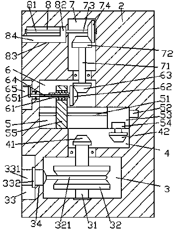
[0021] Such as Figure 1-Figure 6 As shown, an improved welding device of the present invention includes a box body 2, a chute 5 is provided at the center of the interior of the box body 2, and a first An empty bin 6, a second empty bin 4 is provided in the box body 2 below the right side of the chute 5, and a storage tank 3 is provided in the box body 2 at the bottom of the second empty bin 4, and the first empty bin 4 The upper right side of the empty bin 6 is provided with a transfer cavity 7, and the first stud 51 is arranged in the chute 5, and the right end of the first stud 51 is connected with the first motor 52, and the first stud 51 is An upwardly extending sliding post 55 and a slider 53 arranged on the right side of the sliding post 55 are threadedly connected, and the upwardly extending section of the sliding post 55 enters the first empty chamber 6 and the internal steering fit is connected with an internal spline Shaft 61, the right side end of the inner spline...


PUM


Abstract

The invention discloses an improved welding device. The improved welding device comprises a box body; a slide slot is formed in the center inside the box body; a first empty bin is arranged in the boxbody above the left side of the slide slot; a second empty bin is arranged in the box body below the right side of the slide slot; an accommodating slot located at the bottom of the second empty binis formed in the box body; a transfer cavity is arranged above the right side of the first empty bin; a first stud is arranged in the slide slot; the right side of the first stud is connected with a first motor; a slide post capable of upwards extending and a slide block arranged at the right side of the slide post are in threaded matched connection with the first stud; an upward extending sectionof the slide post enters the first empty bin, and the inner part of the upward extending section is rotatably matched and connected with an inner spline shaft; the right side end of the inner splineshaft is fixedly equipped with a first fluted disc; an outer spline shaft is in matched connection with the interior of the inner spline shaft; and a second fluted disc is in matched connection with the upper part of the right side of the first fluted disc. The improved welding device is simple in structure, is convenient to operate, can realize manual control of a lamp panel to stretch out and draw back and automatic control of take-up work, improve take-up efficiency and reduce electric supply waste; and moreover, an illuminating function is provided, so that power supply safety is improved.

Description

technical field [0001] The invention relates to the technical field of welding, in particular to an improved welding device. Background technique [0002] At present, electric welding machines are more and more widely used. However, due to the relatively short power supply line of the electric welding machine, it often affects the movement of the electric welding machine during welding. In the past, one or more wires are generally used for similar phenomena. The board is lengthened and connected to achieve the purpose of plugging and powering the electric welding machine. However, after multiple terminal boards are connected, the power supply line has a certain length, which is extremely inconvenient when retracting. Ground, so the power supply line is vulnerable to various accidental damages, such as people stepping on it, scratches by hard objects, etc., which will cause damage to the outer insulation of the power supply line and reduce the life of the power supply line; a...

Claims


Application Information

Patent Timeline
IPC IPC(8): H01R13/72F21V33/00
CPCH01R13/72F21V33/00
Inventor 金飞
Owner PUJIANG ANHENG IMPORT & EXPORT
Why Eureka
Try Eureka