Controller for yarn changer

A controller and thread device technology, used in textiles and papermaking, weft knitting, knitting, etc., can solve problems such as control errors, large shock and vibration, affecting production, etc., and achieve improved stability, small shock and vibration, and stable work. Effect

Active Publication Date: 2017-09-05
TANGSHAN WUGU ELECTROMECHANICAL EQUIP CO LTD
View PDF8 Cites 0 Cited by
  • Summary
  • Abstract
  • Description
  • Claims
  • Application Information

AI Technical Summary

Problems solved by technology

[0002] The thread changer is used for circular knitting machines. Each thread changer installed in the circular machine is equipped with several colored yarns. During the weaving process, the thread changer makes the colored yarns participate in the weaving according to the requirements of the knitting process, and weaves multi-color horizontal For a piece of fabric, the controller of the existing thread changer drives the internal yarn selection knife to swing after receiving the system signal, and selects the yarns involved in weaving. After selection, it needs to cooperate with the triangle of the knitting machine to drive the push-pull rod of the thread changer The clamping and cutting yarn driven by the thread changer leads the yarns participating in the weaving to the weaving area. In actual use, there are usually large shocks and vibrations, it is difficult to install and debug the push-pull rod of the thread changer and the triangle of the knitting machine, and the controller is unstable. In some cases, it is easy to cause control errors and affect production, and the structure is complicated, and it is impossible to realize the independent control of yarn selection and yarn introduction of the thread changer

Method used


Image

  • Controller for yarn changer
  • Controller for yarn changer
  • Controller for yarn changer

Examples


Embodiment Construction

[0025] The present invention will be further described below in conjunction with the examples, the purpose is only to better understand the contents of the present invention, therefore, the examples given do not limit the protection scope of the present invention.

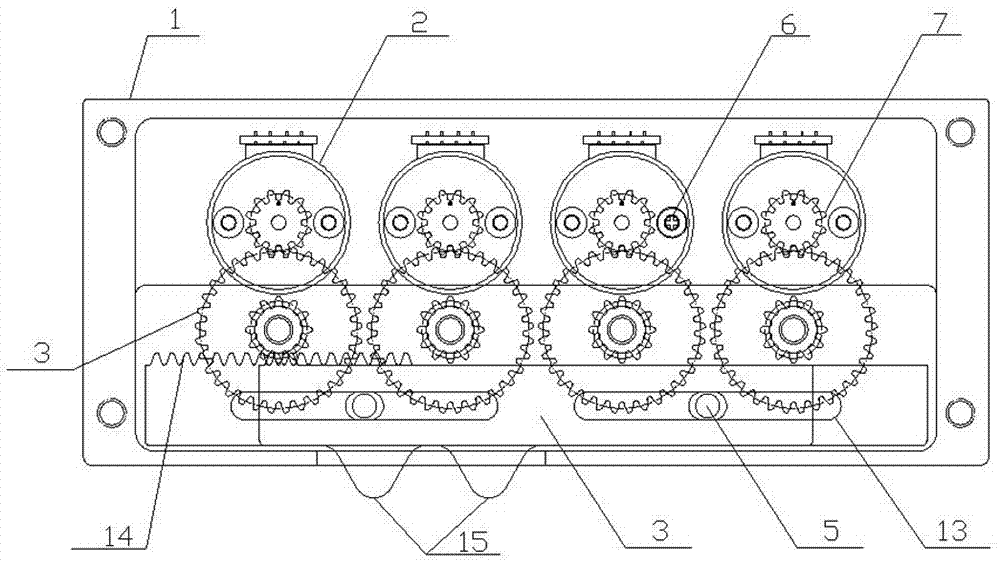
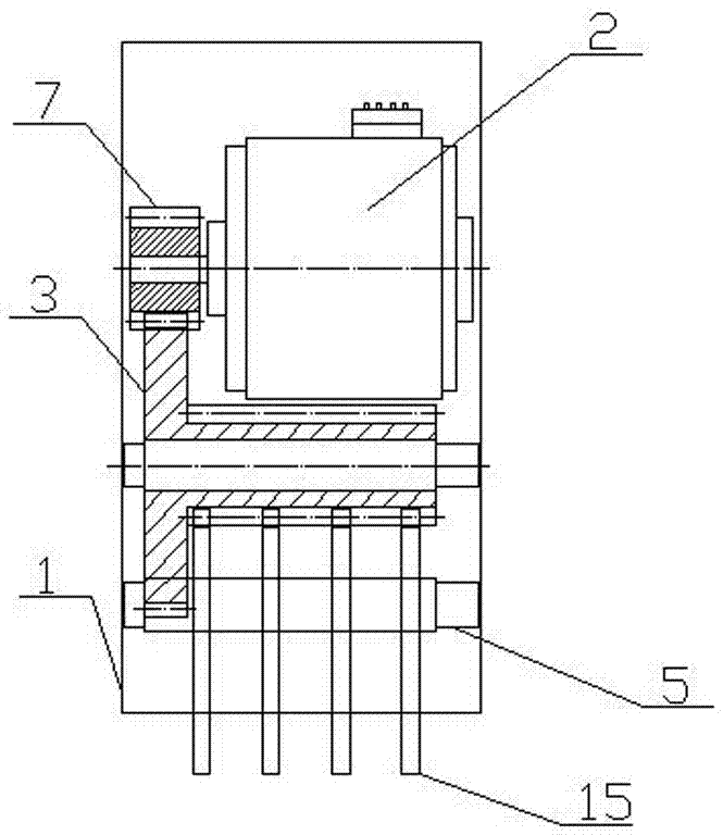
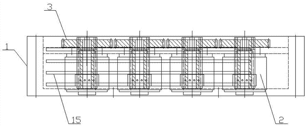
[0026] see figure 1 , figure 2 , image 3 , Figure 4 , Figure 5 , Figure 6 , Figure 7 , Figure 8 , including the controller framework 1 installed on the outer plate 12 of the main body of the wire changer, and also includes a transmission rod 4, a digital circuit 11, and a drive mechanism for driving the transmission rod 4 to perform linear motion. The drive mechanism includes a drive motor and a reducer 2 , speed change gear 3, drive motor and reducer 2, and digital circuit 11 are fixedly installed on the controller frame 1 through bolts 6 respectively, and speed change gear 3 and transmission rod 4 are installed on the controller frame 1 through pin shaft 5 respectively, and the transmission rod 4 is...


PUM


Abstract

The invention relates to a knitting machine and particularly relates to a controller for a yarn changer. The controller comprises a controller skeleton arranged on an outer plate of a yarn changer main body, a transfer bar, a digital circuit and a drive mechanism for driving the transfer bar to carry out linear motion, wherein the transfer bar is connected with the controller skeleton in a sliding manner; the transfer bar drives a yarn clamping and shearing device of the yarn changer to complete yarn selecting and yarn guiding actions while carrying out linear motion; the digital circuit and the drive mechanism are arranged on the controller skeleton separately; and the digital circuit is electrically connected with a drive mechanism. External drive is not needed, and the drive mechanism can be controlled to drive the transfer bar to carry out linear motion by virtue of the digital circuit, so that the transfer bar drives the yarn clamping and shearing device to complete the yarn selecting and yarn guiding actions, and independent control on yarn selecting and yarn guiding of the yarn changer is achieved; and the controller is small in impact vibration, high in applicability, stable in working, simple in structure and beneficial to improvement of the production stability of the knitting machine.

Description

technical field [0001] The invention relates to a knitting machine, in particular to a controller used on a thread changer. Background technique [0002] The thread changer is used for circular knitting machines. Each thread changer installed in the circular machine is equipped with several colored yarns. During the weaving process, the thread changer makes the colored yarns participate in the weaving according to the requirements of the knitting process, and weaves multi-color horizontal For a piece of fabric, the controller of the existing thread changer drives the internal yarn selection knife to swing after receiving the system signal, and selects the yarns involved in weaving. After selection, it needs to cooperate with the triangle of the knitting machine to drive the push-pull rod of the thread changer The clamping and cutting yarn driven by the thread changer leads the yarns participating in the weaving to the weaving area. In actual use, there are usually large shoc...

Claims


Application Information

Patent Timeline
IPC IPC(8): D04B15/60D04B15/94
CPCD04B15/60D04B15/94
Inventor 张燚
Owner TANGSHAN WUGU ELECTROMECHANICAL EQUIP CO LTD
Why Eureka
Try Eureka