Automatic swing and stirring foaming device

A stirring and foaming, automatic technology, applied in the field of foaming aluminum foaming, can solve the problems of vortex formation, uneven distribution of gas bubbles, increase of foaming chambers, etc., and achieve the effect of uniform distribution of bubbles

Active Publication Date: 2017-09-05
盐城福万家保温板有限公司
View PDF5 Cites 4 Cited by
  • Summary
  • Abstract
  • Description
  • Claims
  • Application Information

AI Technical Summary

Problems solved by technology

[0004] The object of the present invention is to address the deficiencies of the prior art, and to provide an automatic oscillating stirring foaming device, which changes the traditional foaming method by setting a pressure regulating gas outlet in the first foaming area and the second foaming area Mechanism, by changing the air pressure of the air intake area and the separation area above the pressure regulating and air outlet mechanism, the aluminum liquid swings left and right to change the position of the center of gravity of the foaming chamber itself, and cooperate with the elastic component at the bottom to increase the strength of the foaming chamber shaking left and right on the elastic component , to form an effect similar to stirring, and at the same time, the gas inlet area supplies gas to the aluminum liquid in the first foaming area and the second foaming area respectively, so that the aluminum liquid continues to foam, which solves the problem of the traditional foaming device during the stirring process. The technical problems of vortex and uneven distribution of gas bubbles have realized the technical effect of fully and evenly foaming aluminum liquid

Method used


Image

  • Automatic swing and stirring foaming device
  • Automatic swing and stirring foaming device
  • Automatic swing and stirring foaming device

Examples


Embodiment

[0060] The embodiments are described below with reference to the accompanying drawings. The embodiments shown below do not limit the invention content described in the claims. required for the solution.

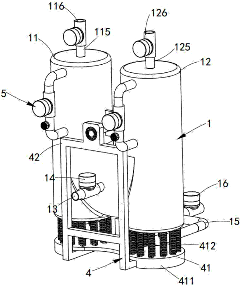
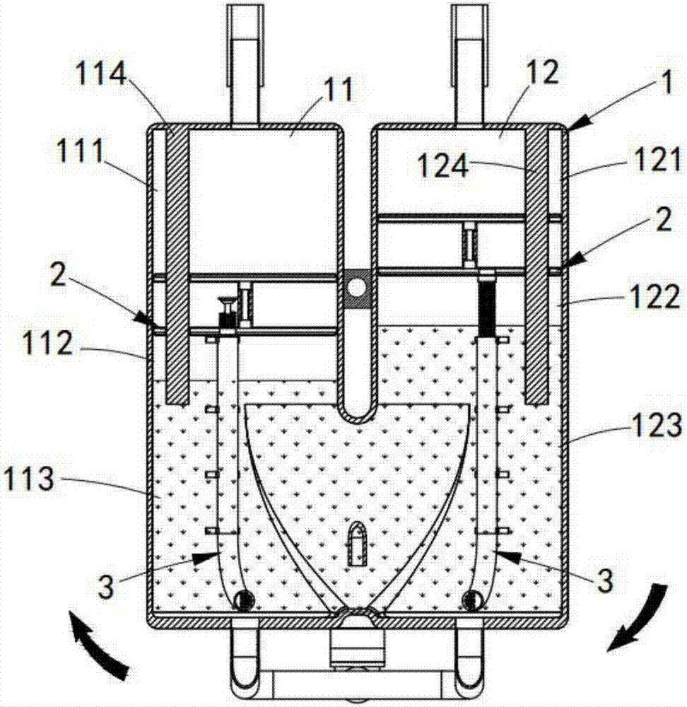
[0061] like figure 1 and figure 2 Shown, an automatic swing stirring foaming device, comprising:

[0062] Foaming chamber 1, said foaming chamber 1 includes a first foaming area 11 and a second foaming area 12 arranged symmetrically, and the bottom of the first foaming area 11 and the second foaming area 12 communicate;

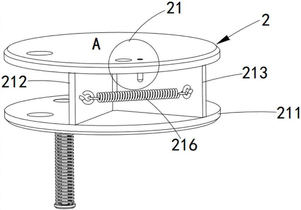
[0063] The pressure regulating air outlet mechanism 2, the pressure regulating air outlet mechanism 2 is respectively arranged in the first foaming area 11 and the second foaming area 12, and it is carried out along the inner wall of the first foaming area 11 and the second foaming area 12. Sliding longitudinally, and it includes a piston assembly 21 and an air outlet switch assembly 22;

[0064] The air injection mechanism 3, the air injection mechanis...

Embodiment approach

[0097] like Figure 11 As shown, as a preferred embodiment, the elastic component 41 includes:

[0098] A base 411, the base 411 is located directly below the foaming chamber 1, and its shape is consistent with the cross-sectional shape of the foaming chamber 1;

[0099] A plurality of springs 412, the springs 412 are respectively arranged below the first foaming area 11 and the second foaming area 12; one end thereof is connected to the base 411, and the other end thereof is connected to the first foaming area 11 It is connected with the lower end surface of the second foaming area 12;

[0100] A plurality of flexible pillars 413 are arranged inside corresponding to the spring 412 and arranged concentrically with the spring 412 .

[0101] like Figure 12 As shown, further, the support assembly 42 includes:

[0102] A support frame 421, the support frame 421 is arranged on both sides of the foaming chamber 1, the bottom of which passes through the base 411;

[0103] A rot...


PUM


Abstract

The invention provides an automatic swing and stirring foaming device which changes the traditional foaming method. Pressure-regulating and air outlet mechanisms are arranged in a first foaming area and a second foaming area, so that molten aluminum is swung right and left to change the center of gravity position of a foaming compartment through changing air pressure of an air inlet area and a partition area above the pressure-regulating and air outlet mechanisms, and by matching with an elastic component arranged at the bottom of the foaming compartment, the force of swinging the foaming compartment right and left on the elastic component is increased to form similar stirring effect; at the same time, the air inlet area is used for inputting gas into the molten aluminum in the first foaming area and the second foaming area separately so that the molten aluminum foams continuously; the technical problems that vortex is formed in the stirring process in the traditional foaming device and the gas bubbles are distributed unevenly are solved, and the technical effect of full and even foaming of the molten aluminum is achieved.

Description

technical field [0001] The invention relates to the technical field of aluminum foaming, in particular to an automatic swinging and stirring foaming device. Background technique [0002] In the existing aluminum liquid foaming method, during the foaming process of the aluminum liquid, the bubbles in the aluminum liquid will float upward from the lower part of the aluminum liquid, and the upper part of the melt has more bubbles than the lower part, resulting in uneven foaming of the foamed aluminum. In order to prevent the bubbles from floating up, the method of adding viscous agent is used in the production process to increase the viscosity of the aluminum liquid and control the bubbles from floating up. The fluidity of the melt before solidification is still very large, causing the bubbles to still float up, causing the melt to foam up and down unevenly, with fewer bubbles at the bottom and higher density, more bubbles at the top and lower density, and poor product qualific...

Claims


Application Information

Patent Timeline
Patent Type & Authority Applications(China)
IPC IPC(8): C22C1/08
CPCC22C1/08C22C1/086
Inventor 丁伟平
Owner 盐城福万家保温板有限公司
Why Eureka
Try Eureka