
Photographing device

A camera device and camera technology, applied in the electronic field, can solve the problems of limited shooting angle and shooting range of the camera of the video surveillance device, the inability to capture the monitoring dead angle, and the inability of the video monitoring device to move freely, so as to avoid the monitoring dead angle and enrich the shooting angle and the effect of shooting range

Pending Publication Date: 2017-09-01
BEIJING XIAOMI MOBILE SOFTWARE CO LTD
View PDF10 Cites 2 Cited by
  • Summary
  • Abstract
  • Description
  • Claims
  • Application Information

AI Technical Summary

Problems solved by technology

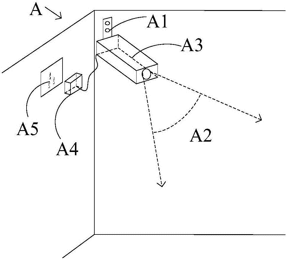
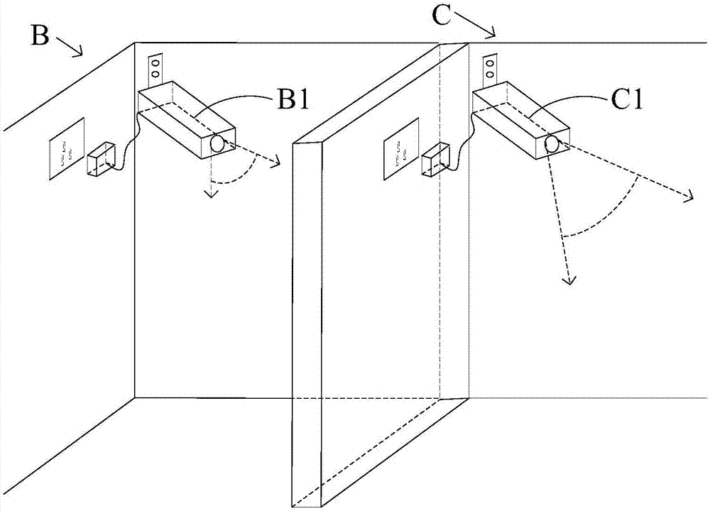
[0003] Since the position of the preset power socket matched with the power plug is fixed, the video monitoring device cannot move freely due to the limitation of the working power supply, and the shooting angle and shooting range of the camera itself of the video monitoring device are limited, so in the related art There are often "monitoring blind spots" that cannot be photographed in the monitoring area of ​​video surveillance devices

Method used


Image

  • Photographing device
  • Photographing device
  • Photographing device

Examples


Embodiment Construction

[0049] Reference will now be made in detail to the exemplary embodiments, examples of which are illustrated in the accompanying drawings. When the following description refers to the accompanying drawings, the same numerals in different drawings refer to the same or similar elements unless otherwise indicated. The implementations described in the following exemplary examples do not represent all implementations consistent with the present disclosure. Rather, they are merely examples of apparatuses and methods consistent with aspects of the present disclosure as recited in the appended claims.

[0050] The camera device involved in the present disclosure can be used in the field of video surveillance in public places, in the field of home video surveillance, and in other work fields that require multi-directional uninterrupted shooting, and the present disclosure is not limited thereto. Taking the home video surveillance scene as an example, the description is as follows:

[...


PUM


Abstract

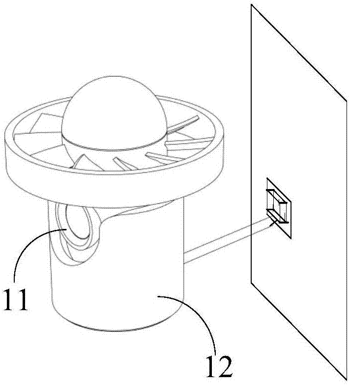
The invention discloses a photographing device which can comprise a charging pile and a photographing main body; the photographing main body can be matched with the charging pile for charging; sufficient electric quantity of the photographing main body is guaranteed through the process, and the photographing device can uninterruptedly carry out photographing work, wherein the photographing main body can comprise a camera and a movement module group; the movement module group can enable the photographing main body to generate movement to move to a target photographing position outside the charging pile; while the camera can photograph images in the movement process of the photographing main body. According to the photographing device, by matching the movement module group with the camera, the photographing main body can be separated from the charging pile and generates movement to change a photographing position so that the photographing main body can carry out no dead angle photographing for a region to be monitored.

Description

technical field [0001] The present disclosure relates to the field of electronic technology, and in particular, to an imaging device. Background technique [0002] In order to ensure the normal operation of the video surveillance device, it needs to provide a stable working power supply. In the related art, the video surveillance device is generally of an integrated structure and equipped with a power plug, which is mated with a fixed preset power socket as a working power source. [0003] Since the position of the preset power socket matched with the power plug is fixed, the video monitoring device cannot move freely due to the limitation of the working power supply, and the shooting angle and shooting range of the camera itself of the video monitoring device are limited, so in the related art There are often "monitoring blind spots" that cannot be photographed in the monitoring area of ​​the video monitoring device. Contents of the invention [0004] In order to overco...

Claims


Application Information

Patent Timeline
Patent Type & Authority Applications(China)
IPC IPC(8): H04N7/18G05D3/12
CPCH04N7/181G05D3/12
Inventor 邢政张磊刘振华
Owner BEIJING XIAOMI MOBILE SOFTWARE CO LTD
Learn More