Three-axis holder, shooting device, shooting system and unmanned shooting system
A technology of shooting system and shooting equipment, applied in the field of unmanned shooting system and three-axis gimbal, can solve the problems of inability to meet shooting requirements, shooting function limitations, etc., and achieve the effect of compact structure, reduced volume, and clear picture.
- Summary
- Abstract
- Description
- Claims
- Application Information
AI Technical Summary
Problems solved by technology
Method used
Image

Examples
Embodiment 1
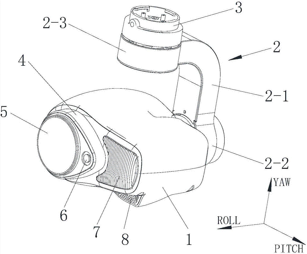
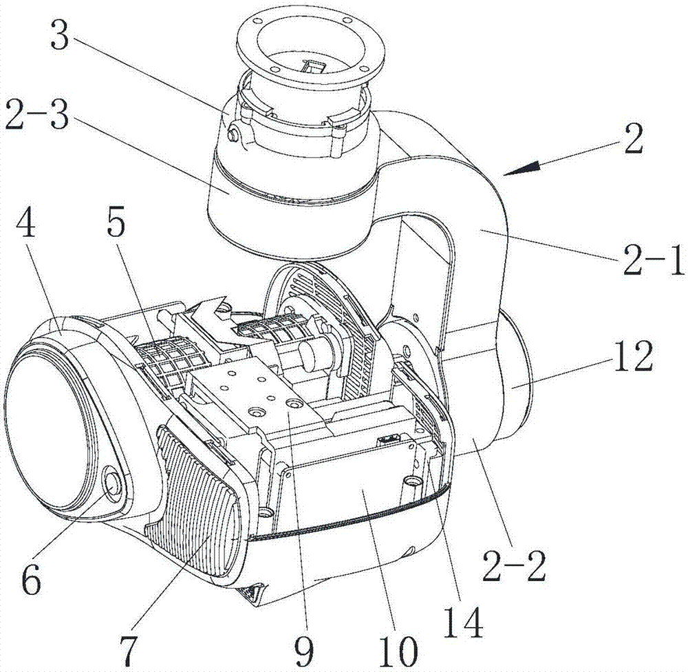
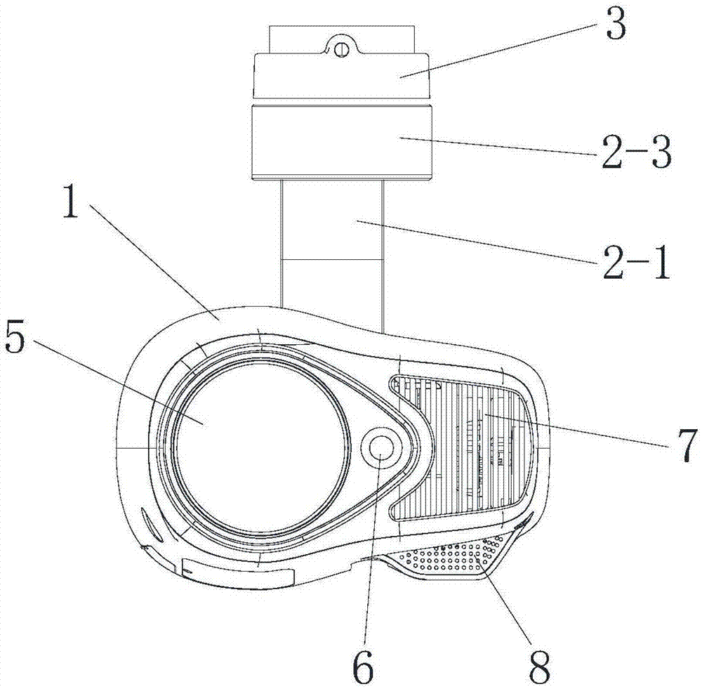
[0061] Such as figure 1 , figure 2 , Figure 10 , Figure 11 Shown is one of the embodiments of the present invention, in this embodiment, a kind of three-axis head, comprises main force arm 2, secondary force arm 11 and chassis 1, and first motor, second motor and the 3rd motor, wherein The third motor (such as a PITCH shaft motor) is located in the chassis 1, one end of the main arm 2 is connected to the stator of the first motor (such as a YAW shaft motor), and the other end of the main arm 2 is connected to a second motor (such as a ROLL shaft motor) One end of the auxiliary moment arm 11 is connected to the rotor of the second motor (such as the ROLL shaft motor), and the other end of the auxiliary moment arm is connected to the stator of the third motor (such as the PITCH shaft motor).
[0062] The main arm 2 and the auxiliary moment arm 11 are the main load-bearing parts of the three-axis gimbal. The upper and lower ends of the main force arm 2 are respectively pro...
Embodiment 2
[0084] In this embodiment, the difference from Embodiment 1 is that the cross section of the main arm is circular or elliptical. The circular or elliptical shape can also meet the load-bearing requirements of the moment arm, and it is also beneficial to further reduce air resistance.
[0085] Other structures are the same as those in Embodiment 1, and will not be described again here.
Embodiment 3
[0087] In this embodiment, a shooting device is provided, and the shooting device includes a binocular lens device and the three-axis pan / tilt described in Embodiment 1 or Embodiment 2.
[0088] The binocular lens device comprises two different types of the first lens and the second lens, the first lens and the second lens are installed in the casing 1, and the first lens and the second lens are located on the same horizontal plane (referring to that the optical axes of the lenses are located on the same horizontal plane ), the first lens and the second lens are fixed together by a structural member (fixed in the chassis 1 to maintain a positional relationship between each other); a predetermined distance is provided between the first lens and the second lens, so that the first lens The angle of view and the angle of view of the second camera do not intersect.
[0089] The first lens captures a first image with a first resolution, and the second lens captures a second image wi...
PUM
 Abstract
Description
Claims
Application Information
 - R&D
- Intellectual Property
- Life Sciences
- Materials
- Tech Scout
- Unparalleled Data Quality
- Higher Quality Content
- 60% Fewer Hallucinations
Browse by: Latest US Patents, China's latest patents, Technical Efficacy Thesaurus, Application Domain, Technology Topic, Popular Technical Reports.
© 2025 PatSnap. All rights reserved.Legal|Privacy policy|Modern Slavery Act Transparency Statement|Sitemap|About US| Contact US: help@patsnap.com