Hybrid-winding linear electromagnetic brake
A linear electromagnetic and hybrid winding technology, applied in permanent magnet clutches/brakes, asynchronous inductive clutches/brakes, electric motors/converter plugs, etc., can solve the problem that the braking force characteristics cannot take into account both high speed and low speed, and the braking force cannot be adjusted , poor dynamic performance and other problems, to achieve the effect of shortening the braking distance, increasing the braking force density and reducing the cost
- Summary
- Abstract
- Description
- Claims
- Application Information
AI Technical Summary
Problems solved by technology
Method used
Image
Examples
specific Embodiment approach 1
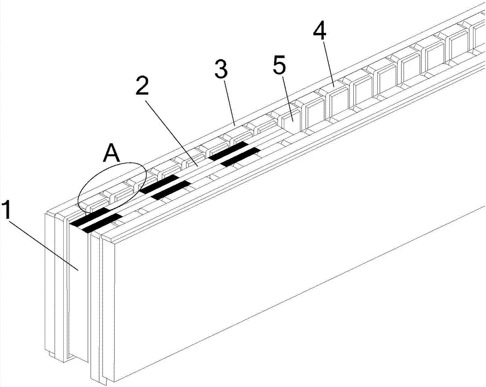
[0030] Specific implementation mode one: refer to Figure 1 to Figure 3 Specifically explain this embodiment, the hybrid winding linear electromagnetic brake described in this embodiment includes a stator, a mover and a multi-phase power converter, and there is an air gap between the stator and the mover;
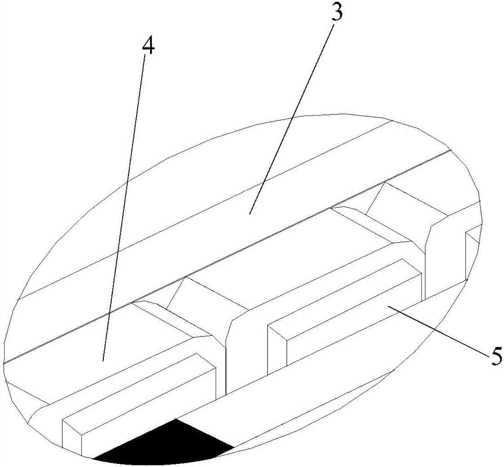
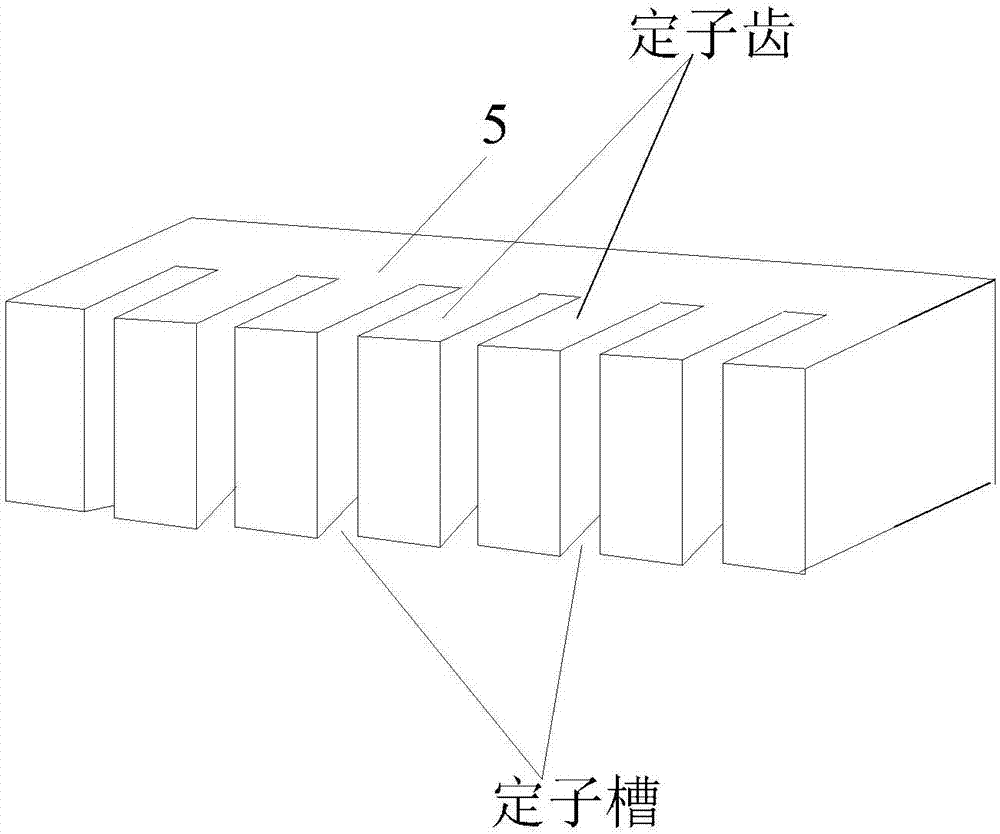
[0031] The stator includes a stator core 5, a cage-type short-circuit winding 3 and a multi-phase AC winding 4; the stator core 5 has a stator slot, and the cage-type short-circuit winding 3 and the multi-phase AC winding 4 are arranged in the stator slot;
[0032] The mover is composed of a mover substrate 1 and a permanent magnet 2;
[0033] The mover substrate 1 is in the shape of a flat plate, and on the side of the mover substrate 1 facing the air gap, strip-shaped primary permanent magnets 2N and S are alternately arranged along the moving direction.
[0034] Both the winding output end of the cage short-circuit winding 3 and the winding output end of the multi-phase...
Embodiment
[0036] like figure 1 As shown, the hybrid winding linear electromagnetic brake is mainly composed of a stator, a mover and a power converter. The stator is mainly composed of a stator core, a cage short-circuit winding and a multi-phase AC winding; the mover is mainly composed of a mover substrate and a permanent magnet; The bar-shaped primary permanent magnets N and S are arranged alternately.
[0037] The hybrid winding linear electromagnetic brake has a double primary structure. The cage short-circuit winding is composed of guide bars and side bars, slots are made transversely on the air gap side of each stator core, and a metal guide bar is embedded in the bottom side of each slot. Metal edging is joined together. Each tooth of the stator core is wound with a coil, and the coil side of each coil is embedded in the notch side of the stator core slot, and each coil is connected into a multi-phase symmetrical winding.
specific Embodiment approach 2
[0038] Specific implementation mode two: refer to Figure 1 to Figure 5 This embodiment is described in detail. This embodiment is a further description of the hybrid winding linear electromagnetic brake described in Embodiment 1. In this embodiment, the air gap side of the stator core 5 is horizontally provided with a stator slot, and the bottom of the stator slot A cage-type short-circuit winding 3 is provided, and a multi-phase AC winding 4 is provided at the notch of the stator slot;
[0039] The cage short-circuit winding 3 includes a plurality of guide bars 3-1 and two side bars 3-2, the two side bars 3-2 are parallel, and the plurality of guide bars 3-1 are perpendicular to the side bars 3-2; each stator A metal guide bar 3-1 is embedded in the bottom side of the slot; a coil is wound on each tooth of the stator core 5, and the coil side of each coil is embedded in the notch side of the stator core slot. The coils are connected to form a multi-phase AC winding 4, and t...
PUM
 Abstract
Description
Claims
Application Information
 - R&D
- Intellectual Property
- Life Sciences
- Materials
- Tech Scout
- Unparalleled Data Quality
- Higher Quality Content
- 60% Fewer Hallucinations
Browse by: Latest US Patents, China's latest patents, Technical Efficacy Thesaurus, Application Domain, Technology Topic, Popular Technical Reports.
© 2025 PatSnap. All rights reserved.Legal|Privacy policy|Modern Slavery Act Transparency Statement|Sitemap|About US| Contact US: help@patsnap.com


