
A rotor core winding processing device

A technology for processing devices and rotor cores, applied in electromechanical devices, manufacturing motor generators, electrical components, etc., can solve the problems of high labor intensity, low degree of mechanization, poor work efficiency, etc., to ensure winding accuracy, reduce Labor intensity and the effect of improving product quality

Active Publication Date: 2019-05-07
浙江硕朗机电配件有限公司
View PDF3 Cites 0 Cited by
  • Summary
  • Abstract
  • Description
  • Claims
  • Application Information

AI Technical Summary

Problems solved by technology

[0003] Existing winding machines are generally equipped with a rotor winding mold, a winding mechanism, and an indexing mechanism for installing the rotor core; the winding mechanism is fixed, and the rotor core is reciprocally moved during winding. Carry out positioning, then move the rotor core back and forth to wind the first set of coils, and then rotate the rotor core by an angle after the first set of coils are wound, then position the rotor core, and then move the rotor core back and forth to wind the second set of coils , the whole process is because the rotor core is constantly reciprocating, so it must be positioned before winding each set of coils, and the winding process is very cumbersome
In the prior art, the rotor is generally loaded manually, and the worker holds the rotor and puts it into the fixture, and then the mechanical arm performs winding processing on it. This kind of feeding method has a low degree of mechanization and poor work efficiency. , the labor intensity is high, and it is difficult to ensure the concentric placement of the rotor and the fixture, which affects the quality of the coil after winding

Method used


Image

  • A rotor core winding processing device
  • A rotor core winding processing device
  • A rotor core winding processing device

Examples


Embodiment Construction

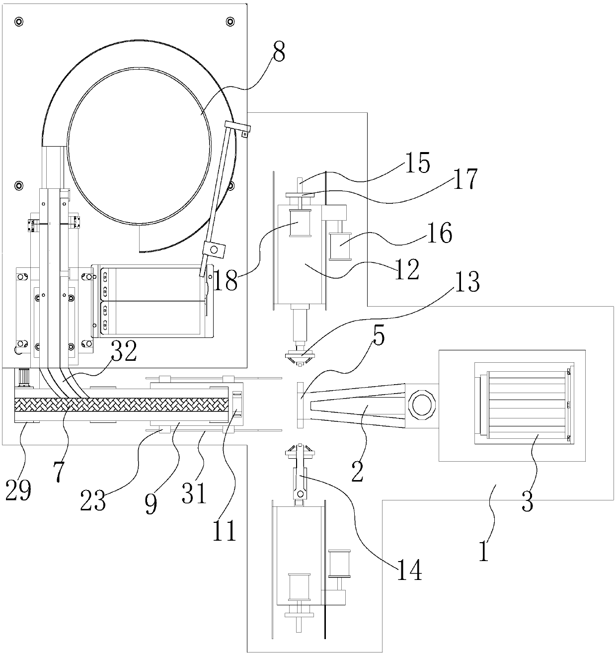
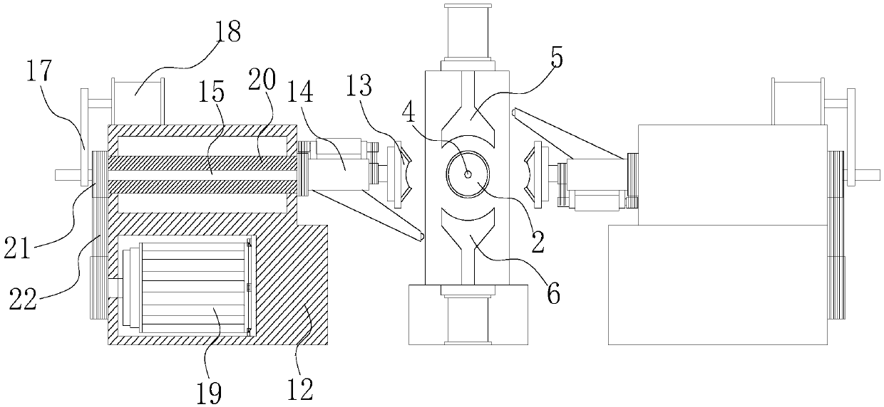
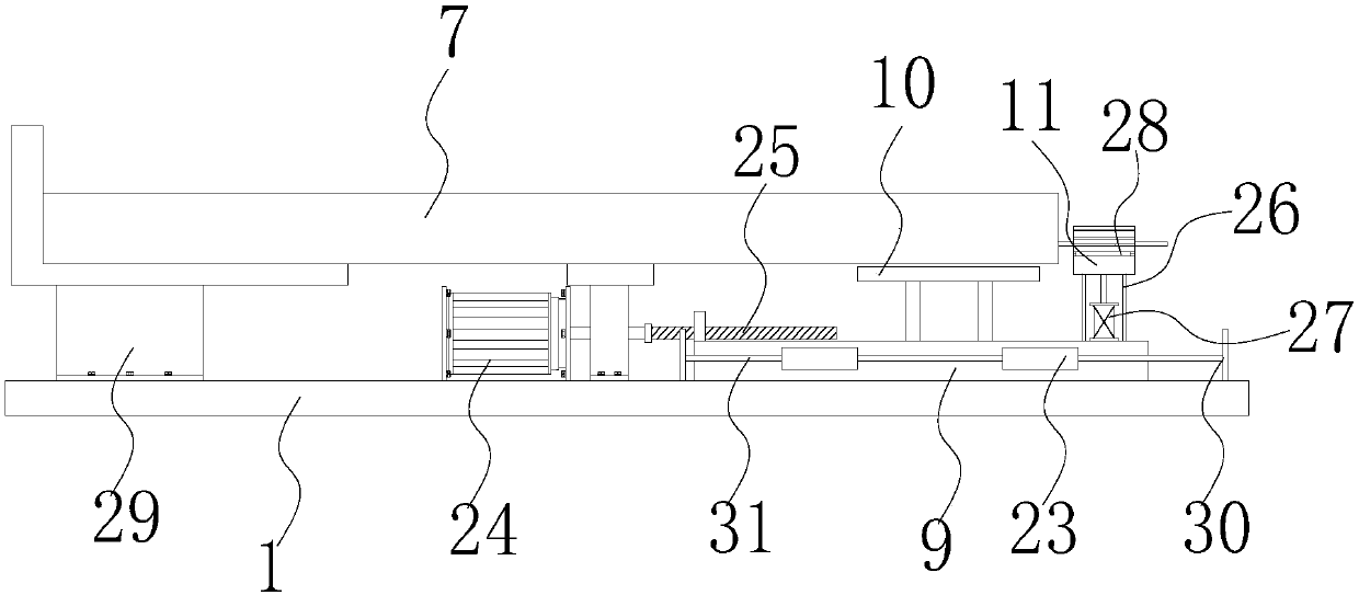
[0021] refer to Figure 1 to Figure 4 , the present invention includes a workbench 1 arranged horizontally, a conveying mechanism for conveying the rotor core, an indexing mechanism for fixing the rotor core, and left and right sides respectively located on both sides of the indexing mechanism. The winding mechanism, the indexing mechanism includes a suction cup sleeve 2 and a servo indexing motor 3 drivingly connected with the suction cup sleeve 2, the connection structure between the servo indexing motor 3 and the suction cup sleeve 2 is the prior art, and the suction cup The outer diameter of the sleeve 2 is smaller than the outer diameter of the rotor core, and one end of the suction cup sleeve 2 is suspended and fixed horizontally on the workbench 1, and the center of the suction cup sleeve 2 is provided with a rotating shaft for the rotor core. Insert the shaft hole 4, the servo indexing motor 3 can drive the suction cup sleeve 2 to rotate several angles, the servo index...


PUM


Abstract

The invention discloses a rotor iron core winding processing apparatus. The rotor iron core winding processing apparatus comprises a working table, a conveying mechanism, an indexing mechanism, a left winding mechanism and a right winding mechanism, wherein the indexing mechanism comprises a sucking disc sleeve and a servo indexing motor; an axle hole for allowing a rotary shaft in a rotor iron core to be placed is formed in the center of the sucking disc sleeve; the conveying mechanism comprises a conveyor belt and a vibration feeding plate; the material outlet of the vibration feeding plate passes through an arc-shaped reversing guiding rail to be connected with the conveyor belt; a material jacking assembly positioned below the conveyor belt is arranged on the working table; and each of the left winding mechanism and the right winding mechanism comprises a base which can move towards the sucking disc sleeve, a protective head used for clamping the rotor iron core and a flying fork used for winding separately. Compared with the prior art, the rotor iron core winding processing apparatus can realize mechanical feeding; the rotor iron core can be jacked continuously and then can be positioned and fixed by the rotary shaft thereof, so that working efficiency is improved and labor intensity is lowered; and the rotor iron core only rotates in the winding and processing, without axial displacement, so that winding accuracy can be ensured and product quality can be improved.

Description

【Technical field】 [0001] The invention relates to the technical field of motor manufacturing equipment, in particular to a rotor iron core winding processing device. 【Background technique】 [0002] The motor is generally composed of a casing, a stator and a rotor. The rotor is provided with a rotating shaft, and the motor rotor is formed by winding the enameled wire into the wire slot of the rotor core by a winding machine. With the development of science and technology, the current motor rotor Processing is usually done by winding directly on the rotor core by a winding machine. [0003] Existing winding machines are generally equipped with a rotor winding mold, a winding mechanism, and an indexing mechanism for installing the rotor core; the winding mechanism is fixed, and the rotor core is reciprocally moved during winding. Carry out positioning, then move the rotor core back and forth to wind the first set of coils, and then rotate the rotor core by an angle after the f...

Claims


Application Information

Patent Timeline
Patent Type & Authority Patents(China)
IPC IPC(8): H02K15/09
CPCH02K15/09
Inventor 黄一波
Owner 浙江硕朗机电配件有限公司
Learn More