Shock absorption shell structure for motor
A motor and casing technology, which is applied in the shock-absorbing casing structure of motors and the field of power machinery, can solve the problems that the motor casing cannot effectively reduce the vibration of the rotor, etc., to facilitate chemical bonding or physical bonding, improve wear resistance and strength, and contact The effect of increasing the area
- Summary
- Abstract
- Description
- Claims
- Application Information
AI Technical Summary
Problems solved by technology
Method used
Image

Examples
Embodiment 1
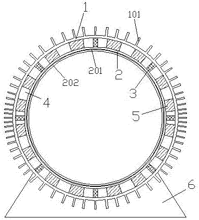
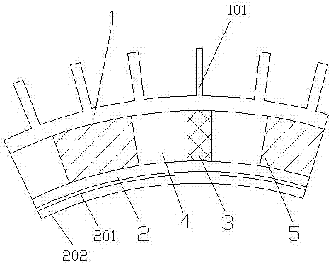
[0050] As shown in the figure, a shock-absorbing shell structure for a motor includes a support 6 and a metal shell 1 fixed on the support 6. The surface of the metal shell 1 is provided with radiating fins 101, and the metal shell 1 is provided with The metal inner shell 2 is separated from it, and the outer wall of the metal inner shell 2 and the inner wall of the metal shell 1 are connected and fixed by a metal support 3, and the compartment 4 between the metal inner shell 2 and the metal shell 1 is filled with several The shock-absorbing rubber block 5 close to the metal inner shell 2 and the metal outer shell 1, and there is a gap between the shock-absorbing rubber blocks 5; the inner wall surface of the metal inner shell 2 is sequentially provided with a metal and ceramic high-temperature bonding layer 201 and The ceramic layer 202 and the metal inner shell 2 are made of an alloy with a melting point higher than 1800°C. The ceramic layer 202 is a ceramic with tiny pores on...
Embodiment 2
[0074] As shown in the figure, a shock-absorbing shell structure for a motor includes a support 6 and a metal shell 1 fixed on the support 6. The surface of the metal shell 1 is provided with radiating fins 101, and the metal shell 1 is provided with The metal inner shell 2 is separated from it, and the outer wall of the metal inner shell 2 and the inner wall of the metal shell 1 are connected and fixed by a metal support 3, and the compartment 4 between the metal inner shell 2 and the metal shell 1 is filled with several The shock-absorbing rubber block 5 close to the metal inner shell 2 and the metal outer shell 1, and there is a gap between the shock-absorbing rubber blocks 5; the inner wall surface of the metal inner shell 2 is sequentially provided with a metal and ceramic high-temperature bonding layer 201 and The ceramic layer 202 and the metal inner shell 2 are made of an alloy with a melting point higher than 1800°C. The ceramic layer 202 is a ceramic with tiny pores on...
Embodiment 3
[0098] As shown in the figure, a shock-absorbing shell structure for a motor includes a support 6 and a metal shell 1 fixed on the support 6. The surface of the metal shell 1 is provided with heat dissipation fins 101, and the metal shell 1 is provided with The metal inner shell 2 is separated from it, and the outer wall of the metal inner shell 2 and the inner wall of the metal shell 1 are connected and fixed by a metal support 3, and the compartment 4 between the metal inner shell 2 and the metal shell 1 is filled with several The shock-absorbing rubber block 5 tightly attached to the metal inner shell 2 and the metal outer shell 1, and there is a gap between the shock-absorbing rubber blocks 5; the inner wall surface of the metal inner shell 2 is sequentially provided with a metal and ceramic high-temperature bonding layer 201 and The ceramic layer 202 and the metal inner shell 2 are made of an alloy with a melting point higher than 1800°C. The ceramic layer 202 is a ceramic ...
PUM
| Property | Measurement | Unit |
|---|---|---|
| melting point | aaaaa | aaaaa |
| diameter | aaaaa | aaaaa |
| length | aaaaa | aaaaa |
Abstract
Description
Claims
Application Information
 - R&D
- Intellectual Property
- Life Sciences
- Materials
- Tech Scout
- Unparalleled Data Quality
- Higher Quality Content
- 60% Fewer Hallucinations
Browse by: Latest US Patents, China's latest patents, Technical Efficacy Thesaurus, Application Domain, Technology Topic, Popular Technical Reports.
© 2025 PatSnap. All rights reserved.Legal|Privacy policy|Modern Slavery Act Transparency Statement|Sitemap|About US| Contact US: help@patsnap.com