
Construction method for reinforcing heat supply pipeline and tee joint

A technology for heating pipes and construction methods, applied in excavation, soil protection, infrastructure engineering, etc., can solve problems such as increasing pipe wall thickness, increasing construction cost, fatigue deformation, etc., to reduce stress damage, increase engineering cost, Effects suitable for implementation

Inactive Publication Date: 2017-08-29
BAOTOU ENG & RES CORP OF IRON & STEEL IND CHINA METALLURGY CONSTR GROUP BERIS
View PDF1 Cites 2 Cited by
  • Summary
  • Abstract
  • Description
  • Claims
  • Application Information

AI Technical Summary

Problems solved by technology

Due to the periodic and repeated temperature changes of the heating pipe itself, fatigue deformation is prone to occur at places with high stress, which eventually leads to damage
The strengthening of the traditional tee structure is only to make a fuss about the strengthening of the component itself, such as increasing the wall thickness of the pipe fittings, selecting prefabricated, drawn-type and other reinforced tees, adding reinforcing plates and other measures, but these measures are in high medium temperature ( Temperature is greater than 90°C), high pressure (pressure greater than 1.6MPa), and large diameter, the deformation and failure rate of the tee are still very high
Infinitely increasing the wall thickness of pipe fittings and adding reinforcement measures will greatly increase the construction cost, and the manufacturing of equipment and materials has a long procurement cycle, and the product qualification rate cannot be guaranteed.
[0003] In addition, during the operation of the heating pipe network in winter, once the tee breaks, it will cause water leakage, and it is difficult to find the fault point. Even if the fault point is found, it will take a lot of time to repair. It is easy to stop heating during the maintenance cause serious social impact

Method used


Image

  • Construction method for reinforcing heat supply pipeline and tee joint
  • Construction method for reinforcing heat supply pipeline and tee joint
  • Construction method for reinforcing heat supply pipeline and tee joint

Examples


Embodiment Construction

[0026] Embodiments of the technical solutions of the present invention will be described in detail below in conjunction with the accompanying drawings. The following examples are only used to illustrate the technical solutions of the present invention more clearly, and therefore are only examples, rather than limiting the protection scope of the present invention.

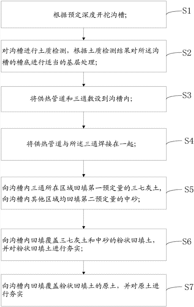
[0027] figure 1 It is a flowchart of a construction method for reinforcing heating pipes and tees according to an embodiment of the present invention, such as figure 1 As shown, the construction method includes the following steps:

[0028] S1. Excavating the trench according to the predetermined depth;

[0029] S2. Carry out soil quality inspection to the trench, and carry out appropriate grass-roots treatment on the bottom of the trench according to the soil quality inspection result;

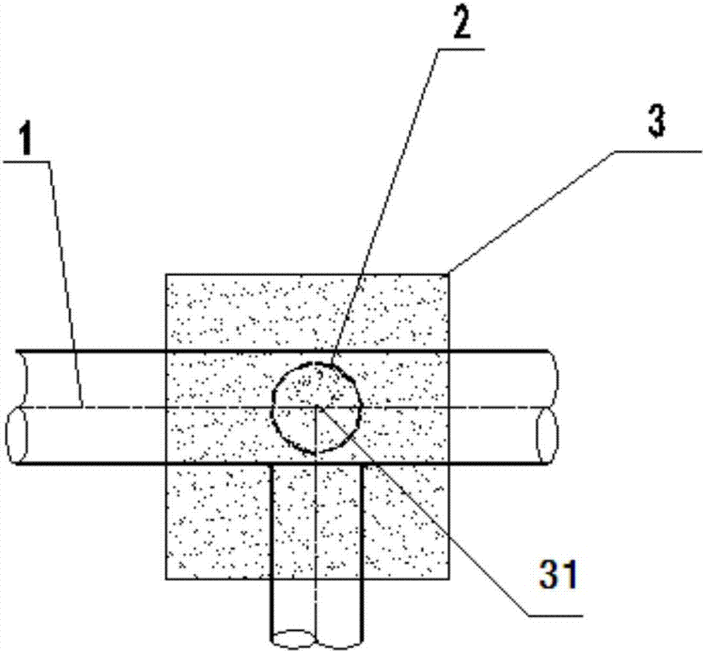
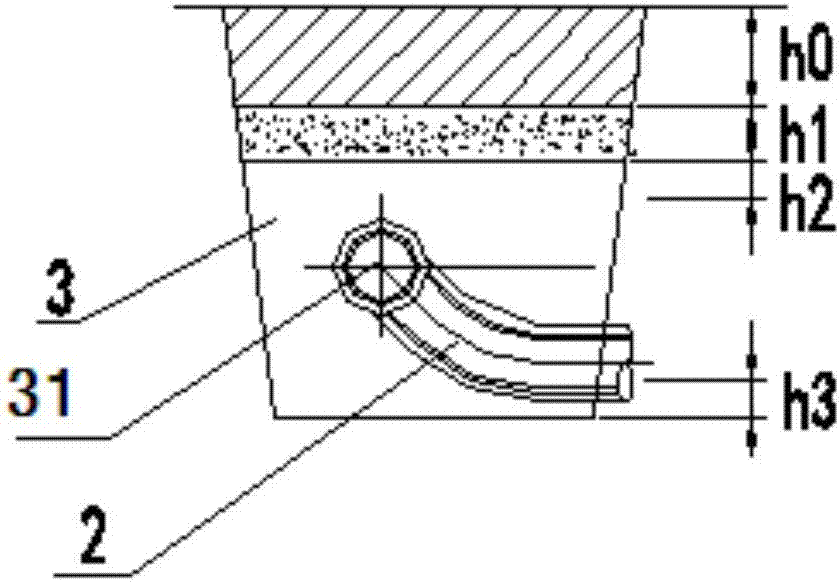
[0030] S3. Laying the heating pipe 1 and the tee 2 into the trench;

[0031] S4, welding the heating pipe 1 and the tee 2 to...


PUM

PropertyMeasurementUnit
Depthaaaaaaaaaa
Thicknessaaaaaaaaaa

Abstract

The invention relates to a construction method for reinforcing a heat supply pipeline and a tee joint. The method comprises the following steps that a trench is dug according to a preset depth; the soil quality of the trench is detected; basic treatment is conducted on the bottom of the trench properly according to the soil quality detection result; the heat supply pipeline and the tee joint are laid in the trench and welded together; a first preset amount of 37 lime soil back fills the area, with the tee joint, in the trench, and a second preset amount of medium sand back fills other areas in the trench; powder backfilling soil for covering the 37 lime soil and the medium sand back fills the trench, and is tamped; and natural soil for covering the powder backfilling soil back fills the trench and is tamped. By adoption of the construction method, the possibility of a stress failure at the tee joint of a heat supply pipe network can be effectively reduced.

Description

technical field [0001] The invention belongs to the field of laying methods of heating pipelines, and in particular relates to a construction method for reinforcing heating pipelines and tees. Background technique [0002] When checking the stress of the entire heating pipe network, the places with high stress are concentrated in the tees, elbows, knuckles and other parts. Due to the periodic and repeated temperature changes of the heating pipe itself, fatigue deformation is prone to occur at places with high stress, which eventually leads to damage. The strengthening of the traditional tee structure is only to make a fuss about the strengthening of the component itself, such as increasing the wall thickness of the pipe fittings, selecting prefabricated, drawn-type and other reinforced tees, adding reinforcing plates and other measures, but these measures are in high medium temperature ( When the temperature is greater than 90°C), the pressure is high (the pressure is great...

Claims


Application Information

Patent Timeline
IPC IPC(8): E02D17/12E02D3/046E02D1/00
CPCE02D17/12E02D1/00E02D3/046
Inventor 田艳荣王强杨旺
Owner BAOTOU ENG & RES CORP OF IRON & STEEL IND CHINA METALLURGY CONSTR GROUP BERIS
Learn More