
band sawing machine

A technology of band sawing machine and bed, which is applied to sawing machine device, sawing machine attachment, metal sawing equipment and other directions, can solve the problems of large reaction force and pressure of saw blade, reduced service life of saw blade, and unsatisfactory application effect, etc. Achieve the effect of improving accuracy, prolonging service life, and obvious shockproof effect

Active Publication Date: 2020-10-27
浙江锯力煌工业科技股份有限公司
View PDF1 Cites 2 Cited by
  • Summary
  • Abstract
  • Description
  • Claims
  • Application Information

AI Technical Summary

Problems solved by technology

[0003] At present, during the use of the band sawing machine, the power system of the band sawing machine will cause the saw band to vibrate, and the saw band itself will vibrate when cutting materials. Therefore, when the band sawing machine is used, the saw band will inevitably vibrate. , and the vibration of the saw band has a great impact on sawing, especially for sawing machines with increased width, the vibration of the saw band will cause rough cut surfaces, the teeth will wear out quickly and become blunt, and the life will be shortened. At the same time, the vibration of the saw band will make abnormal noise , forming noise, the actual application effect is not ideal
[0004] The Chinese invention patent with the patent number of 201510257252.7 discloses a saw blade damping mechanism, which achieves the shock absorption effect by pressing the saw blade with a pressing block. The reaction force and pressure on the saw blade are too large, which will easily damage the saw blade and reduce the service life of the saw blade

Method used


Image

  • band sawing machine
  • band sawing machine
  • band sawing machine

Examples


Embodiment Construction

[0026] The present invention will be further described below in conjunction with accompanying drawing:

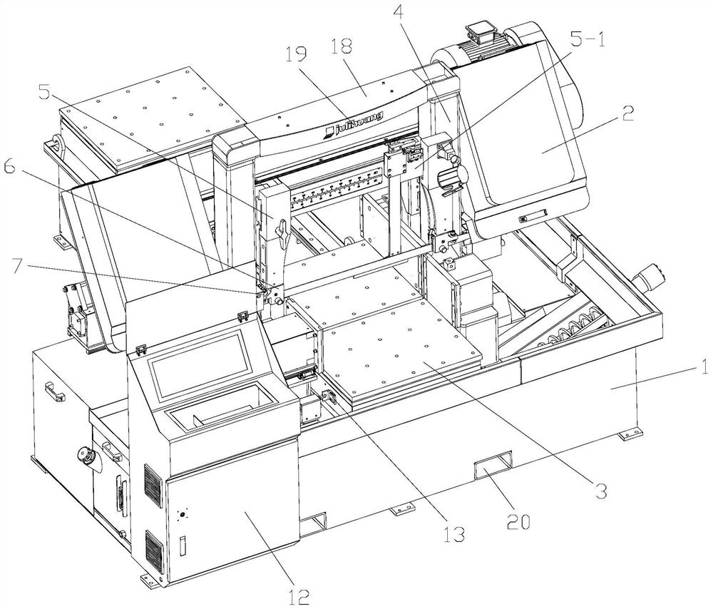
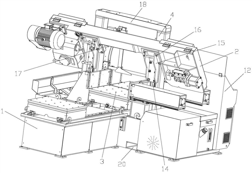
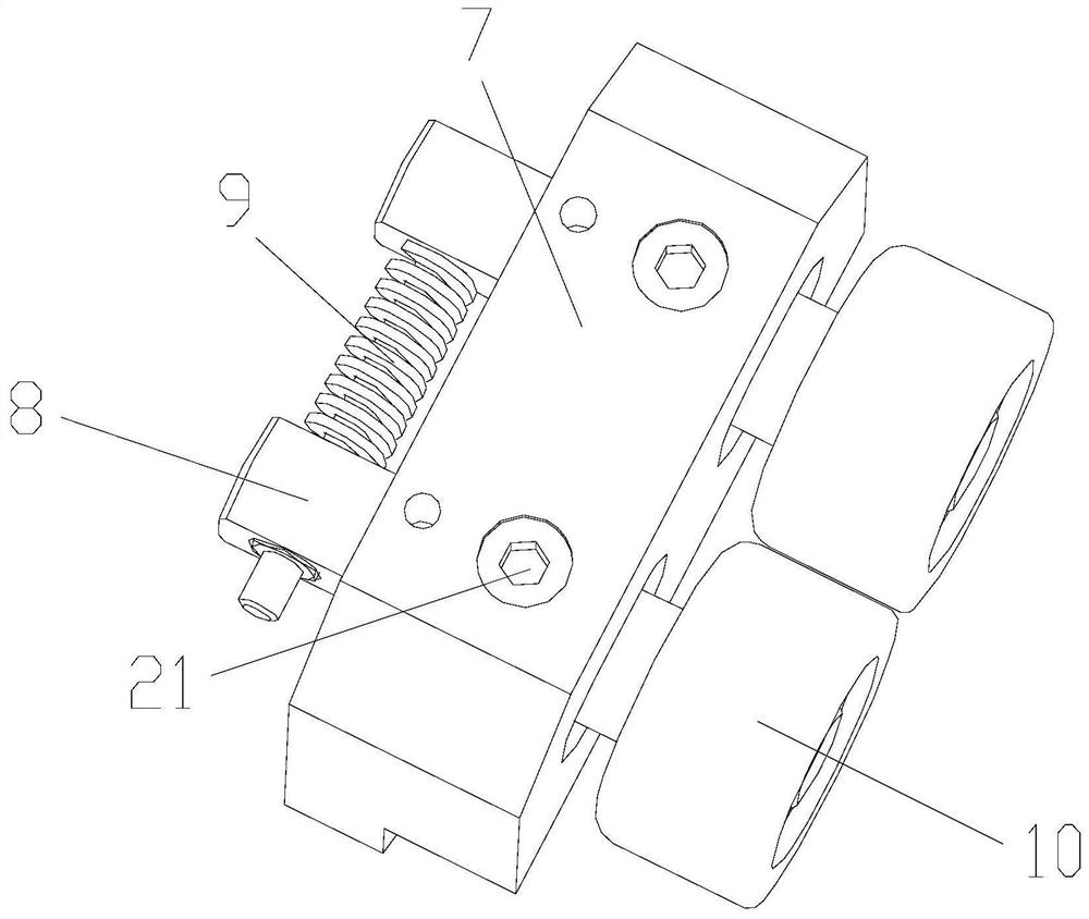
[0027] Referring to the accompanying drawings: this band sawing machine in the present embodiment comprises a bed 1, a saw frame 2 is arranged on the bed 1, a workbench 3 is arranged in the saw frame 2, and the worktable 3 is arranged on the bed 1, and the saw frame 2 is arranged on the bed 1. Two columns 4 are arranged in the frame 2, and the two columns 4 are arranged on the bed 1 and are respectively located on both sides of the workbench 3. A guide arm 5 is arranged between the two columns 4, and a guide seat is installed on the guide arm 5. 6. An anti-vibration seat 7 is installed on the guide seat 6, and the anti-vibration seat 7 is located on one side of the column 4. Two swing shafts 8 are arranged in the anti-vibration seat 7, and a spring 9 is arranged between the front parts of the two swing shafts 8. All are connected with roller 10 on the rear portion of each s...


PUM


Abstract

A bank sawing machine comprises a machine body, wherein a saw frame is arranged on the machine body; a workbench is arranged in the saw frame; two vertical columns are arranged in the saw frame; guiding arms are arranged between the two vertical columns; a guiding seat is mounted on each guiding arm; a shockproof seat is mounted on each guiding seat; two swinging shafts are arranged in each shockproof seat; a spring is arranged between the front parts of every two swinging shafts; two rolling wheels are connected onto the rear parts of every two swinging shafts; and a saw belt clearance is left between every two rolling wheels. The bank sawing machine provided by the invention has the beneficial effects that the shock of a saw belt can be reduced and even eliminated when the bank sawing machine is in use; the shockproof effect is obvious; the service life of the saw belt is prolonged; the material section precision is improved; and the saw cutting noise is reduced.

Description

technical field [0001] The invention relates to the technical field of band sawing machines, in particular to a band sawing machine. Background technique [0002] Band sawing machine is a machine tool used for sawing various metal materials. According to the structure, it is divided into horizontal and vertical; according to the function, it is divided into semi-automatic, fully automatic and numerical control. The horizontal type can be divided into double column and scissor type. The band sawing machine is mainly used for sawing various alloys and metal materials such as carbon structural steel, low alloy steel, high alloy steel, special alloy steel, stainless steel, and acid-resistant steel. [0003] At present, during the use of the band sawing machine, the power system of the band sawing machine will cause the saw band to vibrate, and the saw band itself will vibrate when cutting materials. Therefore, when the band sawing machine is used, the saw band will inevitably v...

Claims


Application Information

Patent Timeline
Patent Type & Authority Patents(China)
IPC IPC(8): B23D55/02B23D55/00B23D59/00B23Q11/00
CPCB23D55/00B23D55/005B23D55/02B23D55/023B23D59/00B23D59/002B23Q11/00B23Q11/0032
Inventor 李斌胜卢勇波宋耀康陈俊亮
Owner 浙江锯力煌工业科技股份有限公司
Learn More