A brushless DC motor electric wheelchair braking device

A brush DC motor and brake device technology, which is applied in transportation and packaging, vehicle rescue, patient chairs or special transportation tools, etc., can solve the problems of large structure, unsafe use, high cost, etc., and achieve convenient use and structure Simple, low-cost effect

Active Publication Date: 2019-04-12
苏州泰原桦诚科技有限公司
View PDF8 Cites 0 Cited by
  • Summary
  • Abstract
  • Description
  • Claims
  • Application Information

AI Technical Summary

Problems solved by technology

[0002] At present, the electric wheelchair brake device mainly refers to electromagnetic brakes, and another electronic brake refers to the braking form during driving. Electromagnetic brakes usually use electromagnets to hold the motor shaft and brake tightly through the action of the mechanism when the electromagnet is powered. When the electromagnet is de-energized, the brake is performed by releasing the motor shaft through the spring, which has the disadvantages of heavy weight, high cost and bulky structure, and wheelchairs are generally used by special groups such as disabled people or patients in the rehabilitation stage. The heavy weight or large structure of the wheelchair may not be convenient for special people to use; while the electronic brake refers to the change of the energization state of the field effect tube through the upper and lower bridge arms under the control of the controller software, so that the A / DC connected to the brushless DC motor The B / C three-phase forms a state similar to a short circuit, thereby making the electric wheelchair brake. Compared with the electromagnetic brake, the above-mentioned electronic brake structure has the advantages of simple structure and convenient control. However, the field effect tube cannot work when the controller is powered off. Those who cannot brake normally have the disadvantage of unsafe use

Method used


Image

  • A brushless DC motor electric wheelchair braking device
  • A brushless DC motor electric wheelchair braking device

Examples


Embodiment Construction

[0014] The technical solutions in the embodiments of the present invention will be clearly and completely described below in conjunction with the accompanying drawings in the embodiments of the present invention. Obviously, the described embodiments are only a part of the embodiments of the present invention, rather than all the embodiments. Based on the embodiments of the present invention, all other embodiments obtained by a person of ordinary skill in the art fall within the protection scope of the present invention.

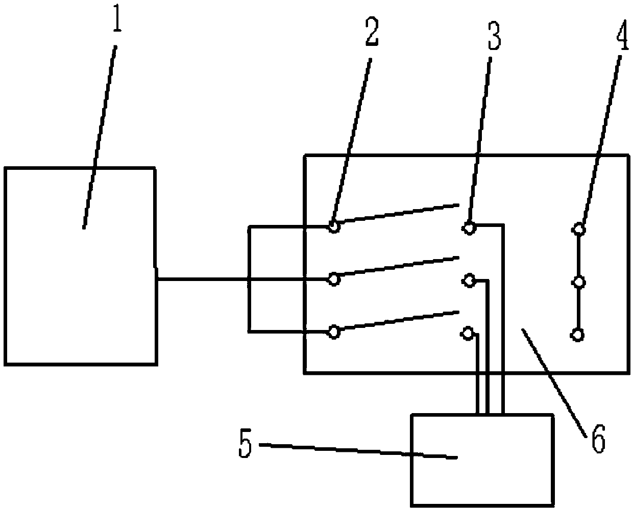
[0015] Such as Figure 1-2 As shown, a brushless DC motor electric wheelchair brake device according to an embodiment of the present invention includes a controller 1. The motor output end of the controller 1 is connected with three normally open contacts 2 of the brake device 6, The brake output end of the controller 1 is connected to the 24V DC wire pack of the brake device 6, the three normally closed contacts 4 of the brake device 6 are electrically connecte...


PUM


Abstract

The invention discloses an electrically powered wheelchair braking device adopting a brushless direct current motor. The braking device comprises a controller. A motor output end of the controller is connected with three normally open contacts of the braking device. A brake output end of the controller is connected with a 24 V direct current coil of the braking device. Three common contacts of the braking device are connected with the brushless direct current motor of an electrically powered wheelchair. The three common contacts are connected with the normally open contacts or normally closed contacts under the driving of an armature. Specifically, the three common contacts are connected with the normally open contacts when the 24 V direct current coil is electrified, and connected with the normally closed contacts when the 24 V direct current coil is not electrified. The three normally closed contacts of the braking device are electrically connected. The braking device has the advantages of being simple in structure, small in size and low in cost, and can be conveniently used by special populations.

Description

Technical field [0001] The invention relates to the technical field of electric wheelchairs, in particular to a brushless DC motor electric wheelchair brake device. Background technique [0002] At present, the electric wheelchair brake device mainly refers to the electromagnetic brake, and the other electronic brake refers to the braking form during driving. The electromagnetic brake usually uses the electromagnet to actuate the electric action, and the motor shaft brake is held by the action of the mechanism. When the electromagnet loses power, the spring releases the motor shaft to brake. It has the disadvantages of heavy weight, high cost and huge structure. Wheelchairs are generally used by special people such as disabled persons or patients in the rehabilitation stage, so The heavy weight or large structure of the wheelchair may not be convenient for special people to use; and the electronic brake refers to the change of the energization state of the upper and lower bridge ...

Claims


Application Information

Patent Timeline
Patent Type & Authority Patents(China)
IPC IPC(8): A61G5/10
CPCA61G5/1032
Inventor 梅虎
Owner 苏州泰原桦诚科技有限公司
Why Eureka
Try Eureka